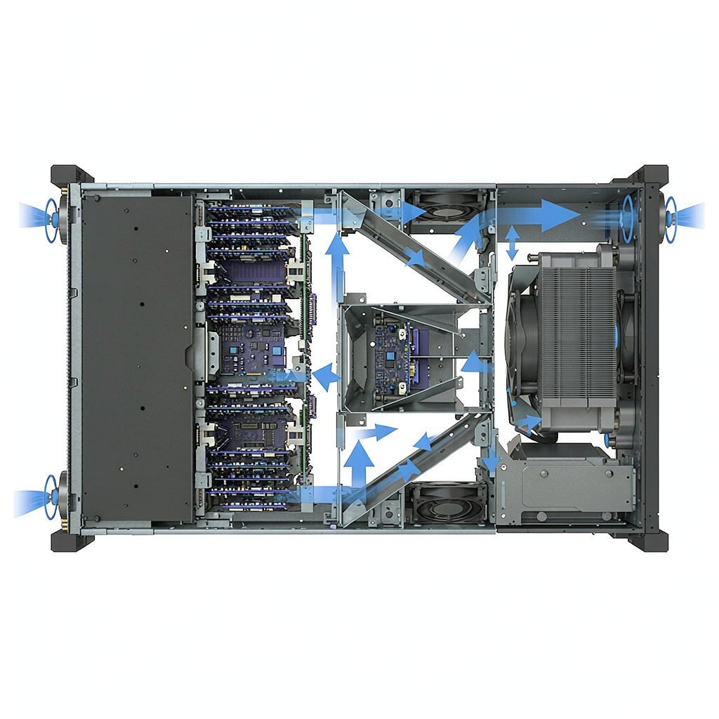
The Short-Circuit Problem
In a typical fan-cooled electronics enclosure, 20–40% of the air moved by the fans can bypass the heat sources entirely—leaking through card gaps, unused slots, and the space around cable bundles—and recirculate from hot exhaust back to the fan inlet. The result is component temperatures 8–15°C higher than the same hardware would reach with a properly baffled path, or alternatively, oversized fans burning extra wattage to compensate. Baffles and seals are the cheapest fix in thermal engineering: sheet-metal parts and gaskets instead of more copper and more CFM.
Where Air Leaks and Recirculates
Slot and drive-bay gaps
Unused PCI slots, empty drive bays, and filler panels removed during maintenance become permanent bypass paths. Rule of thumb: every open slot in a rack chassis leaks roughly 10–15 CFM at typical fan static pressure. Blank all unused positions; EMI blanking panels do double duty for both airflow and shielding.
Fan-to-wall leakage
Mounting a fan against a cutout with a corner gap wastes 5–10% of its flow. Use a shroud or gasket the full fan perimeter, and keep the cutout area within 90–110% of the fan’s active diameter. Finger guards recessed into the panel seal better than flush-mounted ones.
Hot exhaust recirculation
If the exhaust port sits within one fan diameter of an intake, or the enclosure breathes from the same room region it exhausts into, heated air loops back. Separate intake and exhaust zones with an internal divider or route exhaust through a duct; a 100 mm standoff with a splash baffle is usually enough for wall-mounted enclosures.
Baffle Strategies That Work
Straight-through flow architecture
Design the enclosure so air enters one face, passes a defined corridor past the boards, and exits the opposite face. Internal sheet-metal partitions enforce this even when operators rearrange wiring. The flow corridor should not be wider than the board stack plus 10–15 mm of clearance on each side; excess width lets air wander around components instead of through the cha
el.
Per-component sealing
For high-power modules (power supplies, motor drives, RF amplifiers), build local ducts from folded aluminum or insulating foam so every watt of airflow is forced through the module’s own fin stack. Oversized gaps around a 500 W module can starve it while overcooling the neighbor—ducting equalizes the split.
Cable routing discipline
Cable bundles draped across intakes act as random baffles. Reserve cable trays along enclosure walls, use comb holders at card exits, and keep bundles below 20% of any intake cross-section.
Verifying the Fix
Three quick measurements tell you whether baffling worked:
- Inlet vs outlet ΔT: total dissipation divided by mass flow. If ΔT matches your calculation, air is going where intended.
- Component-to-inlet rise: spot-thermocouple the hottest component. A 5°C drop after sealing gaps is common.
- Smoke or fog visualization: a cheap incense stick at the intake reveals recirculation loops in seconds.
For new designs, a two-hour CFD run before cutting metal costs less than one rework cycle. But most enclosure overheating in the field is not a simulation problem—it is ten missing blanking panels and a cable bundle over the fan.
Maintenance Rules
Inspect baffles and gaskets on the same schedule as filter changes. Vibration loosens fan gaskets; service technicians rarely reinstall blanking panels correctly. A laminated airflow map on the enclosure door—showing intended intake, exhaust, and all blanked positions—turns every maintenance visit into a correction opportunity instead of a slow leak.



