## The Soldering Challenge of Heavy Copper SMT Boards
Heavy copper PCBs—those with copper weights of 3 oz (105 μm) to 10 oz (350 μm) and beyond—present a unique thermal challenge during SMT reflow soldering. The same copper thickness that enables high current capacity and superior thermal spreading also creates enormous thermal mass that resists uniform heating in a standard convection reflow oven. Components on heavy copper boards experience significant temperature differentials during reflow, with pads co
ected to wide copper pours and internal planes lagging 20-40°C behind isolated pads on the same board.
This thermal non-uniformity drives the primary defect mechanisms in heavy copper SMT assembly: incomplete solder wetting on plane-co
ected pads, component tombstoning from asymmetric wetting, BGA void formation from uneven heating, and intermetallic compound growth variation across the board. Two reflow technologies—convection and vapor phase—address this thermal challenge through fundamentally different heat transfer mechanisms, with significant implications for process yield, void performance, and production throughput.
Understanding the physics behind both methods enables electronics manufacturers to select the optimal reflow technology for their specific heavy copper applications, balancing thermal performance against capital cost, throughput, and operational complexity.
## Convection Reflow: The Industry Standard
### Heat Transfer Mechanism
Convection reflow ovens transfer heat to the PCB through forced hot gas (typically nitrogen or air) circulated by fans across multiple temperature zones. Heat reaches the board surface through two mechanisms: convective heat transfer from the moving gas stream to the board surface, and radiative heat transfer from the heated oven walls and heating elements.
The heat flux delivered to a specific location on the board depends on:
– Gas temperature at that zone (controlled by zone setpoint)
– Gas velocity across the board surface (fan speed and nozzle design)
– Local thermal mass of the board at that location (copper weight, component density, ground plane coverage)
The critical limitation: gas velocity and temperature are uniform across the board, but local thermal mass varies by 10-50x between a thin signal trace and a heavy copper plane. Equal heat input + unequal thermal mass = unequal temperature rise rates.
### Performance on Heavy Copper Boards
On a 4 oz copper board with mixed component types, convection reflow typically produces these thermal variations:
| Metric | Light Copper Zone (1 oz) | Heavy Copper Zone (4 oz) | Delta |
|—|—|—|—|
| Peak temperature | 248°C | 228°C | 20°C |
| Time above liquidus (217°C) | 65 seconds | 28 seconds | 37 seconds |
| Preheat ramp rate | 2.2°C/s | 1.1°C/s | 50% slower |
| Soak time (150-200°C) | 80 seconds | 55 seconds | 25 seconds |
| Cooling rate | 3.5°C/s | 1.8°C/s | Nearly 2x slower |
A 20°C peak temperature differential between light and heavy copper zones is the primary cause of defects. Pads in heavy copper areas may barely reach liquidus temperature (217°C for SAC305) while light-copper pads exceed 245°C. This forces process engineers into an uncomfortable optimization: raise peak temperature to ensure heavy-copper areas wet properly (risking component damage and board delamination), or lower peak temperature to protect light-copper areas (risking cold joints on plane-co
ected pads).
### Void Formation in Convection Reflow
Convection reflow’s thermal gradients contribute directly to void formation in BGA and QFN packages:
– Temperature gradient-driven outgassing: Flux volatiles in solder paste outgas at different rates depending on local temperature—hotter areas complete outgassing before solder melts and traps volatiles, while cooler areas may still be outgassing as the solder solidifies
– Uneven wetting progression: Pads reach liquidus at different times, causing solder to wet pad surfaces in a non-simultaneous sequence that traps flux bubbles at interfaces
– Convection flow disturbance: High-velocity gas streams can physically disturb solder paste deposits on small components before reflow temperature is reached
Typical void rates for heavy copper convection reflow range from 15-30% for QFN thermal pads and 10-20% for BGA balls in X-ray inspection, exceeding the IPC-7095 Class 3 void limit of 25% for BGA and the industry best-practice target of <10% void area.
## Vapor Phase Reflow: Condensation Heat Transfer
### Heat Transfer Mechanism
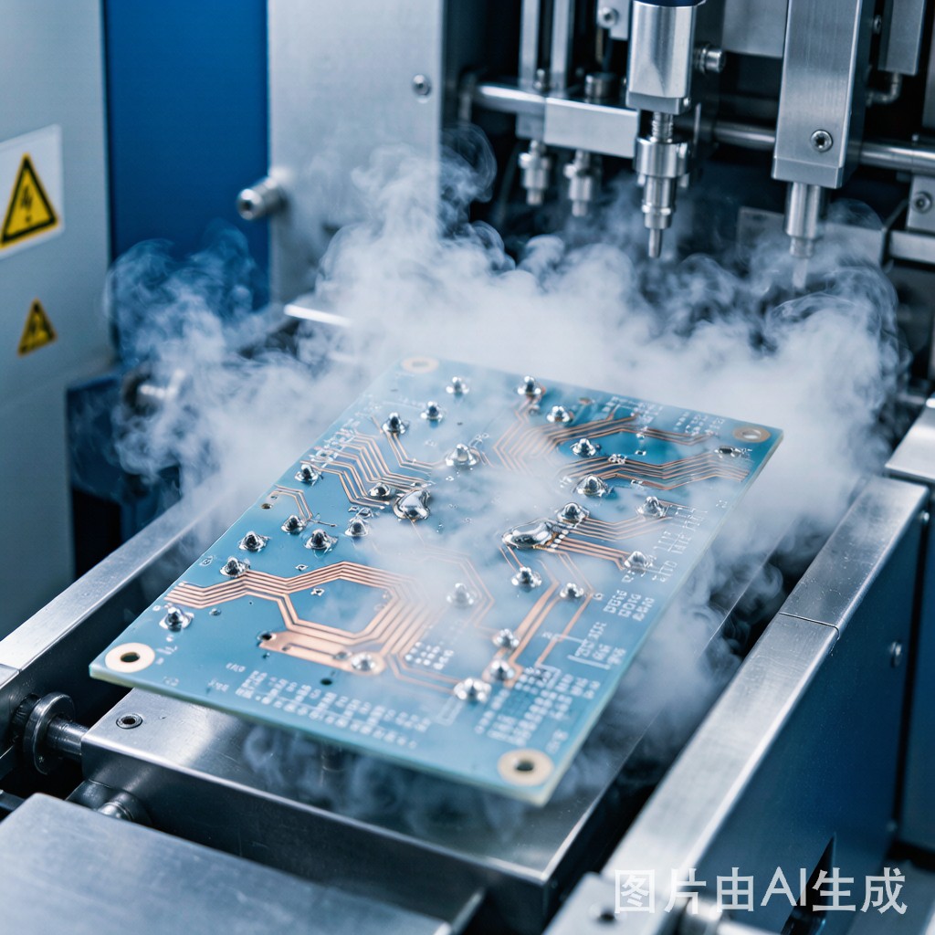
Vapor phase reflow (also called condensation soldering) uses the latent heat of vaporization released when a saturated vapor condenses on the cooler PCB surface. A perfluoropolyether (PFPE) heat transfer fluid—typically Galden or similar—is boiled in a chamber, creating a dense vapor blanket above the liquid. The PCB passes into this vapor zone, and the vapor condenses uniformly on all surfaces cooler than the vapor's boiling point.
The physics are fundamentally different from convection:
– Phase-change heat transfer: Condensation releases 80-100 kJ/kg of latent heat, delivering far more energy per unit surface area than hot gas convection at the same temperature
– Self-limiting temperature: The vapor temperature equals the fluid’s boiling point (typically 230°C or 240°C depending on fluid selection)—the PCB ca
ot exceed this temperature regardless of exposure duration, eliminating overheating risk
– Geometry-independent heating: Vapor condenses on every exposed surface simultaneously, regardless of orientation, shadowing, or component density—a BGA ball on a heavy ground plane receives the same heat flux as an isolated chip capacitor
### Physics of Uniform Heating
The uniform heating capability of vapor phase reflow derives from the condensation mechanism itself. Consider a heavy copper area and a light-copper area on the same board exposed to vapor at 230°C:
1. Both areas start at the same initial temperature (ambient or preheat)
2. Vapor condenses on both surfaces, releasing latent heat at the same rate per unit area
3. The heavy copper area absorbs this heat into its larger thermal mass, so its surface temperature rises more slowly
4. The condensation rate on the heavy copper area remains higher because its surface temperature remains below the vapor saturation temperature longer
5. This self-regulating feedback—more condensation on cooler surfaces—naturally compensates for thermal mass differences
The result: heavy and light copper areas reach the same saturated vapor temperature, with the timing difference compressed from 35-50 seconds in convection to 5-15 seconds in vapor phase.
### Temperature Delta Data: Convection vs Vapor Phase
| Board Type | Convection ΔT (Max) | Vapor Phase ΔT (Max) | Improvement |
|—|—|—|—|
| 2 oz copper, mixed components | 8-15°C | 2-5°C | 3-5x reduction |
| 4 oz copper, power electronics | 15-25°C | 3-7°C | 4-6x reduction |
| 6 oz copper, heavy bus bars | 20-35°C | 5-10°C | 3-7x reduction |
| 10 oz copper, extreme thermal mass | 30-50°C | 8-15°C | 3-4x reduction |
| Mixed 1 oz / 4 oz zones | 18-28°C | 3-8°C | 4-7x reduction |
This thermal uniformity directly translates to improved solder joint quality across all board regions.
### Void Reduction Performance
Vapor phase reflow demonstrates significantly lower void rates compared to convection reflow for heavy copper boards, based on published SMTA and IPC APEX studies:
| Component Type | Convection Void Rate | Vapor Phase Void Rate | Reduction |
|—|—|—|—|
| QFN thermal pad (4 oz board) | 18-28% | 5-12% | 55-65% |
| BGA balls (4 oz board) | 12-22% | 3-8% | 60-70% |
| Power MOSFET tab (6 oz board) | 20-35% | 5-15% | 50-60% |
| Through-hole fill (10 oz board) | 25-40% | 8-18% | 50-55% |
The void reduction mechanism is twofold: (1) uniform heating means all pads reach liquidus nearly simultaneously, allowing flux volatiles to escape before any single pad traps them; (2) the absence of flowing gas means no physical disturbance of paste deposits.
## Operational Comparison: Convection vs Vapor Phase
### Throughput and Process Integration
| Parameter | Convection Reflow | Vapor Phase Reflow |
|—|—|—|
| Typical cycle time | 4-7 minutes (inline) | 6-10 minutes (batch, including fluid recovery) |
| Throughput | 60-120 boards/hour (inline conveyor) | 20-40 boards/hour (single chamber batch) |
| Multi-chamber batch capacity | N/A (inline) | 30-60 boards/hour (2-chamber system) |
| Pre-heat requirement | Integrated in oven zones | Optional separate pre-heat station |
| Cooling | Integrated cooling zone | Separate cooling after vapor chamber |
| Fluid cost | N/A (gas or air) | $500-2000/liter (Galden), 2-5% loss per cycle |
| Nitrogen consumption | 15-30 m³/hour (for N₂ atmosphere) | Minimal (vapor displaces oxygen naturally) |
| Maintenance | Conveyor, fan, heater element cleaning | Fluid level monitoring, filtration, distillation recovery |
### Capital Cost and ROI
Vapor phase reflow systems carry higher capital cost ($80K-250K vs $40K-150K for comparable convection ovens) plus ongoing fluid costs. However, for heavy copper applications, the ROI case emerges from:
– Reduced defect rate: 3-5% defect reduction on heavy copper boards = 30-50 fewer defective boards per 1000, saving $300-2500 per defective board (rework or scrap cost)
– Eliminated reflow profiling: Vapor phase requires no thermal profiling—the fluid boiling point determines peak temperature; this saves 2-4 engineering hours per product changeover
– Higher first-pass yield: Improved wetting consistency reduces inspection fails requiring rework
– Expanded process window: Self-limiting temperature eliminates risk of component damage from overheating, allowing more aggressive profiles for difficult boards
The payback period for vapor phase investment in heavy copper manufacturing typically ranges from 12-24 months in high-mix environments, shortening to 6-12 months in dedicated high-volume heavy copper production.
## Application Selection Guide
### When Convection Reflow is Optimal
– Standard copper weight (1-2 oz) with uniform copper distribution
– High-volume inline production requiring >60 boards/hour
– Existing convection oven infrastructure already deployed
– Products without extreme copper weight or mix variations
– Cost-sensitive consumer electronics where thermal margins are generous
### When Vapor Phase Reflow is Optimal
– Heavy copper boards (3 oz and above) or mixed-weight designs
– Power electronics with large thermal mass components (IGBTs, power MOSFETs, bus bars)
– High-reliability applications where void rates must meet <10% targets (aerospace, medical, automotive)
– Products with severe thermal mass variation across the board (mixed 1 oz and 6 oz zones)
– Small-batch, high-mix production where profiling time cost is significant
– Lead-free soldering where the narrow process window benefits from uniform temperature
### Hybrid Approaches
Some manufacturers deploy both technologies for different product families:
– Convection for standard products (1-2 oz, consumer electronics) at high volume
– Vapor phase for heavy copper products (3 oz+, power/industrial) at lower volume
– Vapor phase for new product introduction (NPI) to eliminate profiling development time, then transfer to convection for volume production
## Conclusion: Technology Selection Based on Thermal Physics
The choice between convection and vapor phase reflow for heavy copper SMT soldering is fundamentally a thermal physics decision. Convection ovens deliver heat through hot gas flowing over the board—simple, well-understood, and cost-effective, but fundamentally limited by the thermal mass non-uniformity of the board itself. Vapor phase reflow delivers heat through condensation of saturated vapor, a self-regulating phase-change mechanism that compensates for thermal mass differences and eliminates overheating risk.
For manufacturers producing heavy copper SMT boards—power supplies, motor drives, automotive electronics, industrial controls, LED lighting—the process yield improvement and defect reduction achieved through vapor phase reflow typically justify the higher equipment and fluid costs within a reasonable ROI period. The uniform heating, lower void rates, and elimination of thermal profiling engineering time combine to produce measurable quality and cost benefits that convection reflow ca
ot match on these thermally challenging products.



