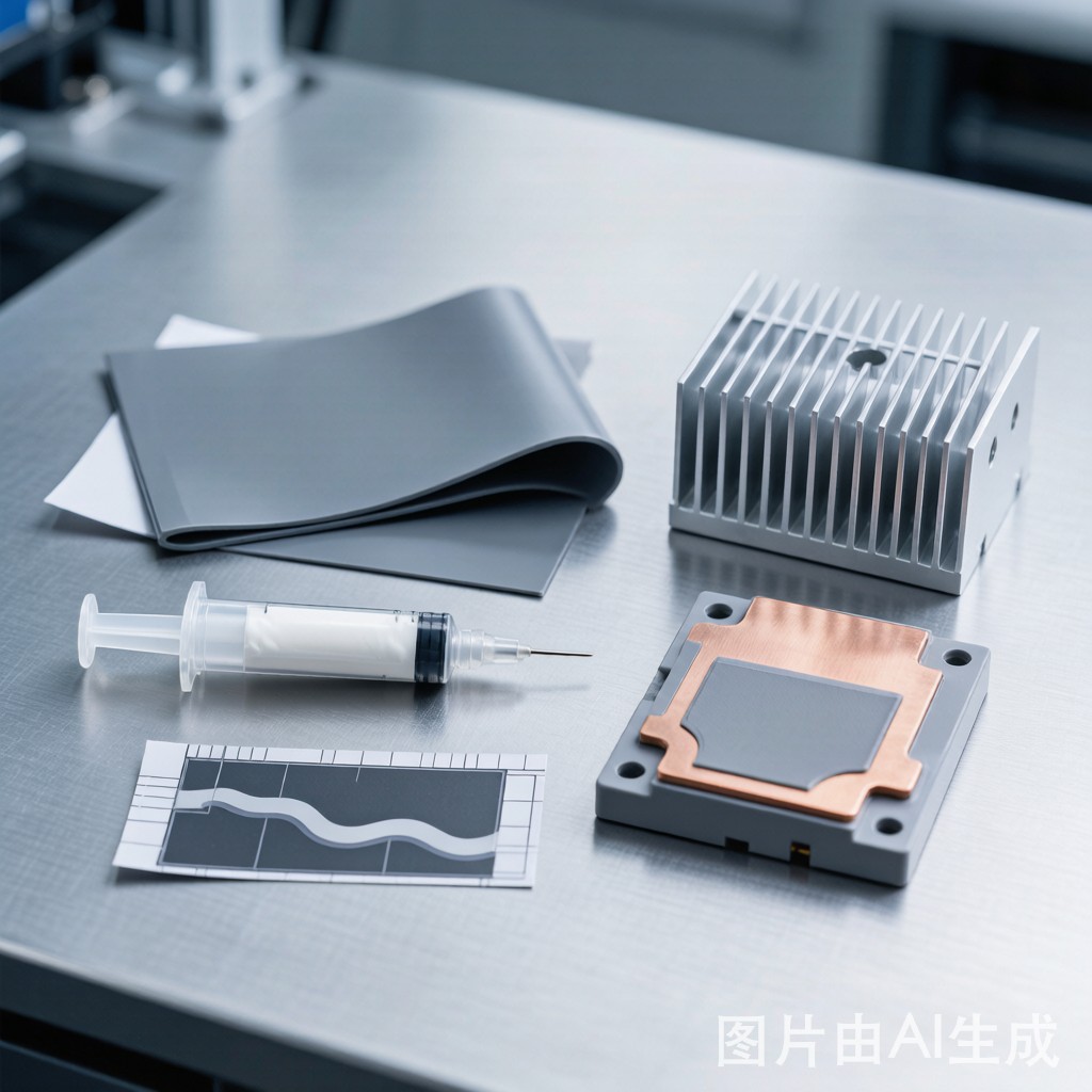
The thermal interface between a power semiconductor package and its heatsink is one of the few remaining high-resistance points in the thermal path from junction to ambient. A power IGBT or MOSFET may have a junction-to-case thermal resistance of 0.1–0.3°C/W — excellent if the case-to-heatsink interface is also low-resistance. But a poorly chosen or applied thermal interface material (TIM) can add 0.5–2.0°C/W at this single interface, more than negating the benefit of the semiconductor’s own low thermal resistance. Selecting the right TIM — thermal pad, thermal grease, or phase-change material — and applying it correctly is a critical thermal management decision in SMT power module assembly.
The Physics of a Thermal Interface
When two solid surfaces are brought into contact — the copper base plate of an IGBT module and the aluminum face of an extruded heatsink — the actual contact area is surprisingly small. At the microscopic level, even a machined flat surface (surface roughness Ra 0.8–3.2 μm) is covered with peaks and valleys. When two such surfaces are clamped together, the peaks make contact — typically only 1–3% of the apparent surface area — and the valleys are filled with air. Since air has a thermal conductivity of 0.026 W/m·K (two orders of magnitude worse than any solid material), the thermal resistance of the air-filled gaps dominates the interface resistance.
A TIM fills these gaps with a material whose thermal conductivity is 1–10 W/m·K — two orders better than air — and whose compliance allows it to conform to the surface roughness of both mating surfaces. The TIM reduces the interface thermal resistance by replacing air with a thermally conductive material that bridges the microscopic gaps.
The total thermal resistance of a TIM joint is:
Rth_total = Rth_bulk + Rth_contact1 + Rth_contact2 = (BLT / k) + Rc1 + Rc2
Where BLT = bond line thickness, k = TIM bulk thermal conductivity, and Rc1, Rc2 = contact resistances at the two interfaces (TIM-to-component and TIM-to-heatsink). The contact resistances depend on surface roughness, clamping pressure, and the TIM’s ability to wet the surfaces.
Thermal Pad (Gap Filler Pad)
Description: A pre-formed sheet of silicone or acrylic elastomer loaded with thermally conductive ceramic fillers (alumina, boron nitride, aluminum nitride, or zinc oxide). Supplied in sheets 0.5–10 mm thick, die-cut to the required shape.
Thermal conductivity: Standard pads: 1.0–3.0 W/m·K. High-performance pads: 5.0–15.0 W/m·K (achieved with high filler loading — 70–90% by weight). The thermal conductivity is measured per ASTM D5470 at a specified pressure (typically 10–50 psi / 70–350 kPa).
Bond line thickness: 0.5–5.0 mm typical. The minimum BLT is determined by the pad’s compressibility and the flatness of the mating surfaces. Pads are typically compressed 10–30% during assembly to ensure good conformity to surface roughness.
Advantages:
- No mess: Solid pad, no liquid to spill, migrate, or contaminate adjacent PCB areas.
- Electrical isolation: Silicone pads have dielectric strength of 10–20 kV/mm. A 0.5 mm pad provides 5–10 kV isolation, sufficient for most power electronics (up to 1,200 V IGBT modules).
- Easy assembly: Peel-and-stick application. The pad is placed on the component or heatsink, the mating surface is aligned, and screws or clips apply clamping pressure. No dispensing equipment needed.
- Conformable to gaps: Thick pads (2–5 mm) can fill significant surface uneve
ess — warped heatsinks, bowed PCB, height variations between multiple components.
- No pump-out: Solid pads do not pump out or migrate under thermal cycling because there is no liquid phase. This is the main reliability advantage of pads over greases.
Disadvantages:
- Higher thermal resistance: Even at high thermal conductivity (5–10 W/m·K), the BLT of a pad is 3–10× thicker than a grease joint, which largely offsets the conductivity advantage. A 5 W/m·K pad at 1.0 mm BLT has Rth_bulk = 0.20 °C·cm²/W. A 3 W/m·K grease at 0.05 mm BLT has Rth_bulk = 0.017 °C·cm²/W — 12× lower.
- Compression set: Silicone pads lose 5–15% of their thickness over time under sustained compression (creep/compression set). This increases BLT slightly (0.05–0.2 mm) and raises thermal resistance during the product’s lifetime.
- Higher cost per application: $0.10–1.00 per pad depending on size and performance grade. Grease is $0.01–0.10 per application.
Thermal Grease (Thermal Paste)
Description: A viscous paste consisting of thermally conductive filler particles (typically zinc oxide, alumina, or silver) suspended in a silicone or hydrocarbon carrier fluid. The paste is applied by dispensing (syringe, pneumatic dispenser, or screen printing) and spreads under clamping pressure to form a very thin bond line.
Thermal conductivity: Standard silicone greases: 1.0–3.0 W/m·K. High-performance greases (silver-filled, diamond-filled): 5.0–10.0 W/m·K. The filler loading is lower than in pads (50–70% by weight) because the paste must remain flowable for dispensing.
Bond line thickness: 25–75 μm (0.025–0.075 mm). This is the key thermal advantage of grease: the thin bond line dramatically reduces bulk thermal resistance, even when the material’s bulk thermal conductivity is modest.
Advantages:
- Lowest thermal resistance: For a given thermal conductivity, grease achieves the lowest interface resistance because the bond line is so thin. A 3.0 W/m·K grease at 50 μm BLT has Rth_bulk ≈ 0.017 °C·cm²/W — better than a 10 W/m·K pad at 1.0 mm BLT (Rth_bulk ≈ 0.10 °C·cm²/W).
- Excellent surface wetting: The liquid carrier fluid fills microscopic surface features, achieving low contact resistance at both interfaces. This is especially important for rough surfaces (Ra > 3 μm) where a solid pad may only contact the highest peaks.
- Low cost per application: $0.01–0.10 per component in production volumes. The dispensing equipment (pneumatic dispenser: $2,000–10,000) amortizes to < $0.01 per application.
- Reworkable: Grease can be cleaned off with isopropyl alcohol and the component or heatsink re-used. No adhesive residue.
Disadvantages:
- Pump-out: This is the dominant failure mode of thermal grease. During thermal cycling (power on → junction temperature rises → case expands → interface gap increases → power off → gap decreases), the differential expansion between the component (CTE ~3–5 ppm/°C for silicon/ceramic) and heatsink (CTE ~23 ppm/°C for aluminum) repeatedly opens and closes the interface gap. This pumping action squeezes the grease out of the interface, leaving voids. Over 1,000–5,000 thermal cycles, pump-out can remove 30–70% of the grease from the interface, increasing thermal resistance by 2–5×.
- Messy application: Grease can contaminate adjacent PCB areas, co
ector pins, and optical surfaces. Manual dispensing is operator-dependent and can produce inconsistent bond line thickness.
- No electrical isolation: Grease is not a dielectric — the bond line is too thin to provide meaningful voltage isolation. An additional insulator (mica sheet, ceramic spacer, or silicone pad) is required if electrical isolation is needed.
- Drying and hardening: Over 3–5 years at elevated temperature (> 100°C continuous), the carrier fluid can evaporate, leaving behind a dry, cracked filler cake with thermal conductivity 2–5× worse than the fresh grease.
Phase-Change Material (PCM)
Description: A material that is solid at room temperature (film or pad form, easy to handle) but softens to a low-viscosity liquid at temperatures above its phase-change temperature (typically 45–65°C), flowing to fill surface irregularities like a grease. When the temperature drops below the transition point, the PCM re-solidifies but remains in the conformed shape. The phase change is typically a melting of a wax-like or polymer matrix loaded with thermally conductive fillers.
Thermal conductivity: 1.5–5.0 W/m·K. The filler loading is typically 40–60% because the material must flow at temperatures above the transition point.
Phase-change temperature: 45–65°C is standard. The material is solid below 45°C for easy handling and placement, and becomes a low-viscosity liquid (viscosity < 1,000 cP) above 55–65°C during initial power-on (burn-in or functional test). Some PCM formulations have a phase-change temperature of 55°C specifically to match the typical burn-in temperature of power modules.
Bond line thickness: 25–100 μm after phase change. The material flows under clamping pressure when heated above the transition temperature, achieving a thin bond line comparable to grease.
Advantages:
- Best of both worlds: Solid film form (easy handling, like a pad) combined with liquid-like wetting at operating temperature (low thermal resistance, like grease).
- No pump-out: Because the PCM re-solidifies when the device cools below the transition temperature, it resists pump-out far better than grease. The solid material ca
ot be pumped out of the interface gap; it melts and re-flows during the hot phase, but it does not migrate because there is no sustained liquid phase at operating temperature (unless the device runs continuously above 65°C).
- No mess: Applied as a film, die-cut to the required shape, with a release liner. Processing is similar to a pad.
- Good surface wetting: When it melts, the PCM flows into surface roughness features, achieving low contact resistance. The wetting is slightly less complete than a grease (because the molten PCM has higher viscosity than most greases at operating temperature — ~500–2,000 cP vs. ~100–500 cP for grease), but still far better than a pad.
Disadvantages:
- Requires burn-in: The thermal resistance of a PCM at first assembly is high — the material is solid and has not yet flowed to fill the surface roughness. The assembly must be heated above the phase-change temperature under clamping pressure (typically during the product’s initial power-on or a dedicated burn-in step) to achieve the rated thermal performance. This adds a process step for products that do not otherwise have a high-temperature burn-in.
- Higher material cost: $0.05–0.50 per application, approximately 2–5× the cost of grease, though still lower than high-performance pads.
- Temperature-limited: If the device operates continuously above the PCM’s phase-change temperature, the material remains liquid, and pump-out can occur — just as with grease. PCMs are not the right choice for devices that run continuously hot (e.g., server CPUs, base station power amplifiers). For power modules with cyclical loading (IGBTs that switch on/off with duty cycle), PCMs are well-suited.
Selection Matrix
| Criterion | Thermal Pad | Thermal Grease | Phase-Change Material |
|---|---|---|---|
| Thermal resistance (typical) | 0.5–3.0 °C·cm²/W | 0.05–0.20 °C·cm²/W | 0.08–0.30 °C·cm²/W |
| Thermal conductivity | 1–15 W/m·K | 1–10 W/m·K | 1.5–5 W/m·K |
| Typical BLT (bond line thickness) | 0.5–5.0 mm | 0.025–0.075 mm | 0.025–0.100 mm |
| Electrical isolation | Yes (5–20 kV/mm) | No | Optional (some films) |
| Ease of assembly | Excellent (peel-and-stick) | Poor (dispense, messy) | Good (film, die-cut) |
| Reworkability | Good (pad removes cleanly) | Fair (requires solvent cleaning) | Good (film removes cleanly) |
| Pump-out resistance | Excellent | Poor (primary failure mode) | Good (solid at room temp) |
| Long-term reliability | Good (compression set is main aging mechanism) | Poor (pump-out, drying over 3–5 years) | Very good (5–10+ years) |
| Material cost per application | $0.10–1.00 | $0.01–0.10 | $0.05–0.50 |
| Best suited for | Consumer, gap-filling, isolated | High-performance, reworkable | Automotive, industrial, cyclic load |
Application Selection Guide for SMT Power Modules
Choose thermal pads when:
- Electrical isolation between the component and heatsink is required (e.g., TO-220 package with exposed tab that is electrically live).
- Multiple components at different heights share a common heatsink, and a compliant pad bridges the height differences.
- Assembly simplicity is the priority — consumer products with automated assembly lines.
- Thermal performance is not the primary constraint (heat dissipation < 5 W per component).
- The product lifetime is short (< 3 years) so compression set is not a concern.
Choose thermal grease when:
- Thermal performance is the primary constraint — every 0.1°C/W matters (high-power IGBT modules dissipating 50–200 W).
- Rework is expected — prototypes, low-volume production, or field-serviceable assemblies.
- Cost per application must be minimized in high-volume production.
- The heatsink surface is not flat (surface flatness > 0.05 mm/mm) and the grease conforms better than a pad.
- The assembly is for a data center, server, or enterprise product where a
ual replacement (re-pasting) is part of the maintenance cycle.
Choose phase-change materials when:
- Thermal cycling reliability is critical — automotive power modules (IGBTs in EV inverters, DC-DC converters), industrial motor drives, and solar inverters that cycle from cold-start to full-power and back daily.
- Pump-out from grease is a known failure mode in the specific application.
- Assembly cleanliness is important — no grease mess, no solvent cleaning step.
- The product undergoes a mandatory burn-in or functional test cycle above the PCM’s phase-change temperature (this “activates” the PCM, flowing it into the surface roughness).
- Long service life (10+ years) is required without re-pasting, and thermal pads do not meet the thermal performance requirement.
For the Southeast Asian power electronics market — EV components, solar inverters, industrial motor drives, and high-power LED lighting — the trend is toward phase-change materials for new designs. The combination of easy assembly (film form), low thermal resistance (comparable to grease), and excellent long-term reliability (no pump-out) makes PCMs the best-balanced choice for most SMT power module applications where thermal performance and reliability are both driving requirements.



