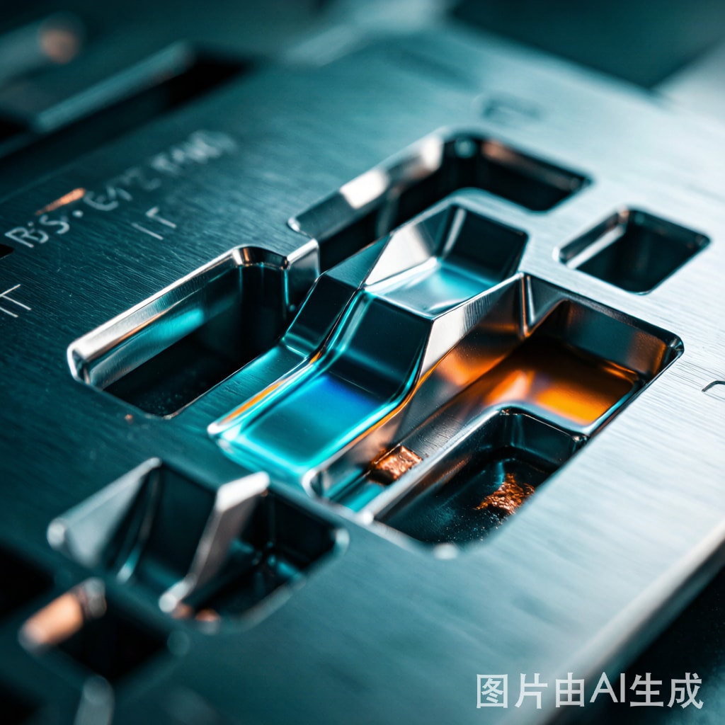
Introduction: The Stencil Becomes the Bottleneck at Sub-Mil Pitch
As SMT assembly pushes toward 01005 chip components (0.4 × 0.2 mm) and the emerging 008004 package (0.25 × 0.125 mm), the printed circuit board’s land pattern stops being the limiting factor. The stencil aperture geometry now determines whether a single solder paste deposit can be released cleanly or whether the assembly line will drown in mid-chip solder balls, random tombstones, and BGA head-in-pillow defects. A laser-cut stainless steel stencil that worked perfectly for 0201 components will fail catastrophically at 01005 because of insufficient aperture wall quality, poor paste release mechanics, and a fundamental area-ratio shortfall. This article examines the manufacturing processes—mechanical polish, electro-polish, and electroforming—that define aperture wall integrity, and provides the engineering data needed to qualify a stencil for high-yield 01005 and 008004 printing.
Aperture Wall Quality: The Hidden Driver of Paste Release
Wall Roughness, Ra, and the Release Mechanism
Solder paste release from a stencil aperture is governed by a force balance between adhesive forces (paste-to-aperture-wall) and cohesive forces (paste-to-paste). When the aperture wall has a high surface roughness (Ra > 1.5 μm), paste adheres to the wall micro-features and resists release, leaving a partial deposit on the PCB pad. This is the dominant failure mode for 01005 apertures, where total paste volume is on the order of 0.0003 mm³ and a 20% release shortfall becomes the difference between a sound joint and an open circuit.
| Wall Finish | Typical Ra (μm) | Process Method | Suitable Aperture Size |
|---|---|---|---|
| Laser-cut as-cut | 3.0–6.0 | CO₂ or fiber laser, no post-process | ≥ 0.5 mm pitch |
| Laser-cut + electropolish | 0.8–1.5 | Acid bath after cutting | ≥ 0.4 mm pitch (0201) |
| Laser-cut + mechanical polish | 0.4–0.8 | Abrasive paste, brushing | ≥ 0.3 mm pitch (01005) |
| Electroformed nickel | 0.2–0.5 | Photo-lithography + Ni plating | ≥ 0.2 mm pitch (008004) |
| Nano-coated electroformed | 0.15–0.3 | Ni + fluoropolymer nano-coat | 008004 and 0.15 mm pitch |
Trapezoidal Aperture Geometry
Laser cutting produces apertures with a slight positive taper (wider at the print side, narrower at the board side) because the laser diverges as it travels through foil thickness. The standard industry specification is a 5° taper per side, yielding a top-to-bottom dimensional difference of approximately 12 μm in a 75 μm stencil. For 01005 apertures (typically 200 × 100 μm top dimension), this taper is significant—it reduces the bottom aperture to 188 × 88 μm, which is below the 200 μm land pattern and risks bridging. Electroformed stencils, by contrast, can be manufactured with a controlled 2° negative taper (board-side wider than print-side) that actively aids paste release by creating a wedge geometry. This ‘reverse taper’ design is unique to electroforming and is one of the key reasons this process dominates ultra-fine-pitch applications.
Electroforming vs Laser Cutting: A Manufacturing Comparison
Laser-Cut Stencil Process
The standard laser-cut stencil is manufactured from 100–150 μm thick stainless steel foil (typically SUS304 with bright a
ealed finish). Apertures are cut using a high-power fiber laser (typically 20–50 W pulsed Yb-fiber at 1064 nm) that vaporizes metal in a controlled kerf. Modern systems achieve ±5 μm positional accuracy and cut apertures as small as 80 × 80 μm. After cutting, the stencil is electropolished to remove the recast layer and heat-affected zone, reducing wall roughness from 3–6 μm Ra to 0.8–1.5 μm Ra.
Advantages: low cost (US$80–200 per stencil), fast turnaround (24–48 hours), excellent for prototypes and low-to-medium volume. Disadvantages: limited aperture wall quality, no negative taper capability, recast layer risk, tapered walls from laser divergence, foil-thickness-dependent geometry.
Electroformed Stencil Process
Electroformed stencils are manufactured through a photo-lithography and electroplating process. A mandrel is coated with photoresist, the aperture pattern is exposed and developed, and nickel is electroplated into the photoresist cavities to the target stencil thickness. After plating, the nickel foil is peeled from the mandrel, frame-mounted, and inspected. The aperture walls inherit the smoothness of the photoresist sidewall (0.2–0.5 μm Ra) and the aperture geometry can be designed with intentional 2° negative taper.
Advantages: ultra-smooth walls, negative taper, no recast layer, consistent quality across aperture sizes. Disadvantages: 3–5× higher cost (US$400–1200), longer lead time (5–10 days), foil thickness limited to 25–150 μm.
Area Ratio and Paste Transfer Efficiency
The Area Ratio Rule
The industry-standard area ratio (AR) defines the minimum aperture size for acceptable paste release:
AR = Aperture Open Area / Aperture Wall Area = (W × L) / (2 × (W + L) × T)
Where W = aperture width, L = aperture length, T = stencil thickness. The widely-cited rule is AR > 0.66 for reliable release, although modern electroformed stencils with nano-coatings can achieve AR = 0.55 with 95%+ transfer efficiency.
Component-Specific Area Ratios
| Component | Pad Size (μm) | Aperture (μm) | Stencil Thickness (μm) | Area Ratio | Recommended Process |
|---|---|---|---|---|---|
| 0201 (0603 metric) | 300 × 250 | 250 × 200 | 75 | 0.74 | Laser + electropolish |
| 01005 (0402 metric) | 200 × 150 | 180 × 130 | 75 | 0.50 | Electroformed (mandatory) |
| 01005 (0402 metric) | 200 × 150 | 180 × 130 | 50 | 0.75 | Electroformed, thin foil |
| 008004 | 130 × 90 | 120 × 80 | 50 | 0.42 | Electroformed + nano-coat (only option) |
| 008004 (advanced) | 130 × 90 | 120 × 80 | 30 | 0.68 | Electroformed, ultra-thin |
Nano-Coatings: A Step Change for Sub-AR 0.66 Printing
Perfluoropolyether (PFPE) and fluorosilicone nano-coatings applied to stencil aperture walls reduce paste adhesion by 60–80%, enabling paste release at area ratios as low as 0.45 with 90%+ transfer efficiency. These coatings are applied by dip-coating or plasma-enhanced chemical vapor deposition (PECVD) at thicknesses of 5–50 nm. The coating also reduces stencil underside paste smearing by 50–70%, which is critical for preventing solder ball defects between adjacent 01005 pads. Coating life is typically 50,000–100,000 print cycles before reapplication is needed, with stencil cleaning performed using isopropanol or specialty stencil wipes every 5–20 prints depending on solder paste type and humidity.
Process Control and Stencil Inspection
Critical-to-Quality Parameters
For 01005 and 008004 stencil qualification, the following parameters must be measured and controlled:
- Aperture dimensional accuracy: ±5 μm (1σ) verified via automated optical inspection at 100% of apertures
- Wall roughness: Ra < 0.5 μm for 01005, Ra < 0.3 μm for 008004, measured by white-light interferometry on witness coupons
- Taper angle: 0° to -2° (negative taper) for electroformed stencils
- Stencil thickness uniformity: ±3 μm across full frame area, measured by laser triangulation
- Positional accuracy: ±10 μm at 4σ for all aperture centers relative to fiducials
Incoming Inspection Protocol
For production stencils used in high-volume 01005 assembly, the recommended incoming inspection protocol includes 100% AOI of all apertures, SPI verification on a coupon board with full-pitch coverage, and a 50-panel production trial before release. The first-article test should measure solder paste volume on at least 30 apertures of each unique size, with Cpk > 1.33 for paste volume as the release threshold.
Conclusion: Choosing the Right Process for the Right Pitch
The selection between laser-cut and electroformed stencils is no longer a cost decision—it is a yield decision dictated by the smallest aperture on the board. For 0201 and larger components, laser-cut stencils with electropolishing deliver excellent results at minimal cost. For 01005 components, electroformed stencils with controlled negative taper are essential, and the additional cost is recovered many times over through reduced rework, higher first-pass yield, and elimination of mid-chip solder ball defects. For 008004 components and below, only electroformed stencils with nano-coatings deliver the area ratio and wall smoothness required for production-grade printing. As the industry continues to miniaturize, the stencil—long considered a commodity—is once again a critical engineering component deserving the same design attention as the PCB itself.



