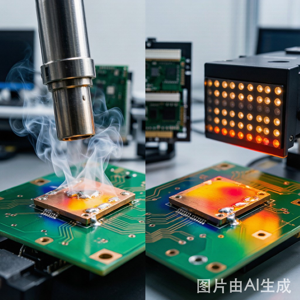
Why Rework Heating Method Matters for Copper Pad Integrity
SMT rework is an unavoidable reality in electronics manufacturing—whether correcting placement errors, replacing defective components, or upgrading field-returned boards. The rework process involves heating a soldered component and its surrounding PCB area to reflow temperature (245-260 degrees C for SAC305), removing the component, and resoldering a replacement. During this process, the copper pads and traces on the PCB are subjected to a second or third thermal cycle that can cause pad lifting, copper delamination, and laminate degradation.
The choice of heating method—hot-air (convection) or infrared (radiation)—significantly affects the thermal profile experienced by the copper pad and surrounding laminate. Each method has distinct advantages, limitations, and damage risks. Understanding these differences is essential for selecting the right rework method for each component type and preventing costly PCB damage.
Hot-Air Rework: Principles and Thermal Characteristics
Heating Mechanism
Hot-air rework stations use a motorized blower to force heated air through a nozzle onto the component and surrounding PCB area. The heated air transfers thermal energy by forced convection—the air stream heats the component package, solder joints, and PCB surface simultaneously. The nozzle is typically sized to match the component footprint (within 2-5 mm) to concentrate heat on the target area.
Thermal Profile Characteristics
Hot-air heating produces a thermal profile with the following characteristics:
- Heating rate: 2-5 degrees C/second for medium airflow settings. This is slower than infrared but provides more controlled ramp-up.
- Temperature uniformity: +/-5 to +/-15 degrees C across the component, depending on nozzle design and airflow uniformity. Larger components (BGA >35mm) experience greater temperature variation.
- Thermal gradient: The air stream creates a localized heat zone with a steep radial gradient. Temperatures drop sharply 5-10 mm beyond the nozzle edge, providing good isolation of adjacent components.
- Time to reflow: 30-90 seconds depending on component size, board thickness, and airflow setting.
Advantages for Copper Pad Protection
Hot-air heating is relatively gentle on copper pads because the forced convection heats the entire joint area uniformly, including the component body and the PCB underside. This multi-directional heating reduces the temperature differential between the pad surface and the surrounding copper, minimizing thermal stress on the pad-to-laminate interface. Additionally, the gradual heating rate (2-5 degrees C/s) allows the FR4 laminate to expand uniformly with the copper, reducing the risk of delamination.
Limitations
- Component displacement risk: The air stream can physically displace small components (0402, 0603) if airflow is too high. Use low airflow settings (<15 L/min) for small components.
- Adjacent component heating: While the radial gradient is steep, adjacent components within 5 mm may reach 150-180 degrees C, potentially causing partial reflow of neighboring joints. Use heat shields (aluminum foil or Kapton tape) on adjacent components.
- Large BGA challenges: For BGA packages larger than 40mm x 40mm, hot-air heating struggles to maintain uniform temperature across the entire package. Edge-to-center temperature differentials of 15-25 degrees C are common, risking incomplete reflow at the center.
Infrared Rework: Principles and Thermal Characteristics
Heating Mechanism
Infrared (IR) rework stations use medium-wave infrared emitters (2-5 micrometer wavelength) positioned above the component. The IR radiation is absorbed by the component package, solder joints, and PCB surface, converting to thermal energy. IR heating is a line-of-sight process—the emitter must “see” the target surface for effective energy transfer.
Thermal Profile Characteristics
- Heating rate: 5-15 degrees C/second for high-power IR emitters. This is significantly faster than hot-air and provides rapid reflow cycles.
- Temperature uniformity: +/-3 to +/-8 degrees C across the component for focused IR systems with beam homogenizers. Better uniformity than hot-air for large components.
- Thermal gradient: IR produces a sharper heated zone boundary than hot-air, with virtually no heating beyond the beam footprint. This provides excellent isolation of adjacent components.
- Time to reflow: 15-45 seconds, significantly faster than hot-air.
Advantages for Large Component Rework
IR heating excels at reworking large BGA packages (40mm+) because the emitter can be sized to match the full package footprint, providing uniform energy distribution across the entire surface. The line-of-sight nature of IR means that energy is deposited directly on the component surface rather than being diluted by air mixing, making it more energy-efficient for large-area heating.
Risks for Copper Pad Damage
- Rapid thermal shock: The 5-15 degrees C/second heating rate can cause thermal shock on copper pads, particularly on thin PCBs (0.4-0.8 mm) where the copper-to-laminate bond is stressed by rapid differential expansion. Pad lifting and delamination risk is 2-3 times higher with IR than with hot-air for the same peak temperature.
- Shadowing effects: Tall components (electrolytic capacitors, co
ectors) adjacent to the rework area block IR radiation, creating cold spots. These shadowed areas may not reach reflow temperature, causing incomplete solder removal.
- Non-uniform absorption: Different surface colors and materials absorb IR radiation at different rates. A black BGA package absorbs more IR energy than a green PCB surface, causing the package to heat faster than the pads. This differential heating can stress the solder joints and pad interface.
- Bottom-side heating required: IR systems typically require a separate bottom-side preheater (hot-air or IR) to prevent board warpage from top-side-only heating. The bottom preheater maintains the board at 100-150 degrees C while the top IR emitter provides the reflow energy.
Comparative Analysis: Hot-Air vs Infrared
| Parameter | Hot-Air | Infrared |
|---|---|---|
| Heating rate | 2-5 C/s (controlled) | 5-15 C/s (rapid) |
| Temperature uniformity (35mm BGA) | +/-10 to +/-15 C | +/-3 to +/-5 C |
| Pad damage risk | Low | Medium-High |
| Adjacent component isolation | Good (5-10mm gradient) | Excellent (sharp boundary) |
| Large BGA (>40mm) | Poor (cold center) | Excellent |
| Small component (0402/0603) | Good (low airflow) | Fair (overheating risk) |
| Rework cycle time | 30-90 seconds | 15-45 seconds |
| Bottom preheater required | Recommended | Mandatory |
| Operator skill level | Medium | High (profile tuning) |
Copper Pad Damage Mechanisms During Rework
Pad Lifting
Pad lifting occurs when the copper pad separates from the FR4 laminate during or after rework. The primary cause is thermal stress from rapid heating or cooling. When the pad reaches 245-260 degrees C while the surrounding laminate is at 100-150 degrees C, the 100+ degree temperature differential creates differential expansion stress at the copper-laminate interface. If this stress exceeds the bond strength of the copper-to-laminate adhesion (typically 1.5-3.0 N/mm for standard FR4), the pad lifts.
Prevention: Use a bottom-side preheater to maintain the board at 120-150 degrees C before applying top-side heating. This reduces the temperature differential to 80-110 degrees C, keeping the thermal stress below the delamination threshold. For IR rework, preheat at 3-5 degrees C/second to 150 degrees C, then switch to high-power IR for the reflow spike.
Pad Cratering
Pad cratering is a more severe form of pad damage where the copper pad tears out a section of the underlying FR4 laminate, creating a crater. This occurs when excessive mechanical force is applied to a hot pad—typically during component removal with vacuum tweezers or tweezers that grip the component body. The solder is still partially molten, and the mechanical pull force is transmitted through the component leads to the pad.
Prevention: Wait 3-5 seconds after reflow temperature is reached before applying removal force. Use a motorized vacuum nozzle with controlled pull force (<2N for small components, <5N for large BGAs) rather than manual tweezers. Never pry a component off the board—always lift vertically.
Trace Damage from Thermal Overshoot
When the rework heating exceeds 270 degrees C (common with IR systems at high power), the copper traces co
ected to the pad can experience thermal degradation. The adhesive bond between the copper trace and the laminate weakens at temperatures above 260 degrees C, and the trace may delaminate or crack under thermal stress. This damage is often invisible immediately after rework but manifests as intermittent open circuits after thermal cycling in the field.
Prevention: Use closed-loop temperature control with a thermocouple attached to the pad or component surface. Set the temperature limit to 260 degrees C maximum. For IR systems, use a pyrometer sensor to monitor surface temperature and modulate emitter power in real-time.
Best Practices for Each Heating Method
Hot-Air Best Practices
- Select nozzle size 2-5 mm larger than the component footprint for optimal airflow coverage.
- Set airflow to 10-20 L/min for small components (0402-0805), 20-40 L/min for QFP/SOIC, and 40-80 L/min for BGA.
- Preheat the board to 100-120 degrees C using a bottom hot-air or IR preheater before top-side heating.
- Ramp at 3-4 degrees C/second to 180 degrees C (preheat zone), then 2-3 degrees C/second to 245-255 degrees C (reflow zone).
- Apply flux paste (RMA type) around the component before heating to improve solder wetting and thermal transfer.
Infrared Best Practices
- Use a bottom-side IR preheater to maintain the board at 120-150 degrees C—mandatory for preventing warpage and pad damage.
- Select an emitter size that matches the component footprint. Oversized emitters heat adjacent components; undersized emitters leave cold edges.
- For dark-colored packages (black BGAs), reduce emitter power by 10-15% to compensate for higher IR absorption.
- Ramp at 3-5 degrees C/second to 180 degrees C, then modulate to 2-3 degrees C/second to peak. Avoid heating rates above 8 degrees C/second above 200 degrees C.
- Use a pyrometer for real-time surface temperature monitoring. Set the temperature ceiling at 260 degrees C to prevent pad and trace damage.
Selecting the Right Method by Component Type
- Chip components (0402, 0603, 0805): Hot-air with small nozzle and low airflow. IR risks overheating these small thermal-mass components.
- SOIC, QFP (up to 20mm): Hot-air with matching nozzle. Good temperature uniformity and controlled heating.
- BGA (20-35mm): Either method works. Hot-air with BGA-specific nozzle provides adequate uniformity. IR provides faster cycle time.
- Large BGA (35mm+): IR with bottom preheater. Hot-air ca
ot maintain uniform temperature on large packages.
- Through-hole co
ectors:
Hot-air for small coectors. For large multi-row co
ectors, use a combination of bottom-side IR preheat and top-side hot-air.
- Shielded components (under EMI can): Hot-air after removing the shield can. IR ca
ot penetrate metal shielding.
Conclusion
Both hot-air and infrared rework methods have distinct roles in SMT rework operations. Hot-air provides gentle, controlled heating that minimizes copper pad damage risk—ideal for small components and boards where pad integrity is critical. Infrared provides rapid, uniform heating that excels at large BGA rework but demands careful thermal profile management to prevent pad lifting and trace damage. The key to successful rework—regardless of heating method—is bottom-side preheating to reduce thermal stress, closed-loop temperature control to prevent thermal overshoot, and gentle component removal after complete solder melt. By matching the heating method to the component type and following pad damage prevention practices, rework operators can achieve first-pass success rates above 95% while preserving copper pad and trace integrity for subsequent resoldering and field reliability.



