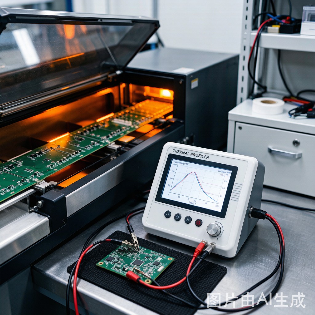
The reflow oven is the heart of any SMT assembly line. A reflow profile that drifts outside the process window — peak temperature too high, time above liquidus too short, cool-down rate too aggressive — will produce solder joint defects at a rate that no amount of AOI inspection or rework can compensate for. The discipline that keeps the oven operating within its validated process window is thermal profiling and calibration. A properly calibrated oven with a regularly-run thermal profile is the foundation of statistical process control for SMT assembly; an uncalibrated oven is a defect-generating machine.
The Two Types of Reflow Oven Calibration
“Calibration” in SMT reflow refers to two distinct but complementary activities:
1. Instrument calibration (oven sensors): Verification that each thermocouple, PID controller, and conveyor speed encoder in the oven reads accurately against a traceable standard. The oven’s internal thermocouples — typically type-K (chromel-alumel), mounted in each heating zone — measure the zone air temperature and feed it to the PID controller. If these thermocouples are reading 5°C low, the PID will command the heaters to 5°C above the setpoint, and every product profile will be incorrect. Instrument calibration is typically performed a
ually or semi-a
ually by a certified metrology technician using a calibrated reference probe placed adjacent to each zone thermocouple.
2. Product-specific thermal profiling (board-level): Profiling the actual PCB assembly as it travels through the oven, using thermocouples attached directly to the board at critical locations (component body, solder joint, board surface). The profiler’s thermocouples measure the real thermal profile that the product experiences, capturing the effects of board mass, component thermal mass, conveyor speed, and zone-to-zone thermal coupling that the oven’s internal sensors ca
ot measure.
Both are necessary. Instrument calibration ensures the oven is heating to the commanded temperatures; product profiling ensures those commanded temperatures are producing the correct thermal experience for the specific product.
Thermal Profiler Equipment: KIC, Datapaq, and Alternatives
Two profiler brands dominate the SMT industry:
| Feature | KIC (KIC Thermal Profiling) | Datapaq (Fluke Process Instruments) |
|---|---|---|
| Thermocouple cha
els |
6–20 (depending on model) | 6–12 (depending on model) |
| Sampling rate | 10–50 Hz per cha
el |
10–200 Hz per cha
el |
| Thermal barrier | Stainless steel + insulation, rated to 300°C for 15 min | Double-wall stainless steel, rated to 300°C for 15 min |
| Software analysis | KIC Navigator (PWI calculation, Cp/Cpk, spec database) | Insight software (profile analysis, PWI, SPC trending) |
| Typical price (6-cha
el) |
$8,000–15,000 | $7,000–12,000 |
| Wireless (real-time) option | KIC ProBot (wired passthrough), KIC Echo (onboard with post-run download) | Datapaq AutoPaq (data logger rides through oven, post-run download) |
Both systems use PWI (Process Window Index) as the primary metric for profile quality. PWI is a dimensionless number that expresses how close the measured profile is to the center of the process specification window:
PWI = 100 × max[(Measured − Center) ÷ (Limit − Center)] across all thermocouple cha
els
- PWI < 100%: Profile is within specification on all parameters.
- PWI < 80%: Profile is comfortably within spec, with margin for process variation. Target for production.
- PWI < 50%: Profile is tightly centered. Indicates a well-optimized oven and low risk of drift-related defects.
- PWI > 100%: Profile exceeds at least one specification limit. Oven settings must be adjusted.
Thermocouple Attachment: The Critical Step
The single largest source of error in reflow profiling is thermocouple attachment. A poorly attached thermocouple can read 5–15°C different from the true temperature at the point of interest, completely invalidating the profile data. Three attachment methods are standard in production:
High-temperature solder attachment: The thermocouple bead is soldered directly to the copper pad or component lead using a high-temperature solder alloy (typically Sn95/Sb5, solidus 232°C, or Sn96.5/Ag3.5, solidus 221°C). The solder joint provides the best thermal conductivity and the fastest response time. This is the gold standard for profiling and is required for critical measurements (BGA ball temperature, QFN thermal pad temperature). The thermocouple must be removed after profiling, and the pad or component must be inspected (or scrapped — most profile boards are designated as sacrificial).
Aluminum tape attachment: The thermocouple bead is pressed against the measurement surface and held in place with aluminum foil tape. This method provides good thermal conductivity (aluminum tape is thermally conductive) and is faster to apply than soldering, but the tape can lose adhesion at peak reflow temperatures (240–260°C) and the thermocouple can lift. Aluminum tape is acceptable for board surface temperature measurements and component body temperatures, but should not be used for solder joint measurements where ±3°C accuracy is required.
Kapton (polyimide) tape attachment: The thermocouple bead is held in place with Kapton tape. Kapton tape has lower thermal conductivity than aluminum tape and can insulate the thermocouple bead from the surface, producing readings that are 3–8°C low. Kapton tape is acceptable for rough profiling and profile verification on non-critical components, but should not be used for high-accuracy measurements.
Thermocouple attachment best practices:
- Use 36 AWG (0.127 mm diameter) type-K thermocouple wire. Thi
er wire has lower thermal mass and faster response time. 30 AWG can be used for more durable setups, but the larger thermal mass slows response by 0.5–1.0 seconds.
- Keep the thermocouple lead wires ru
ing along the board surface (not looping into the air) for at least 10 mm from the measurement point. This minimizes heat conduction away from the bead through the wire, which can cause a 2–5°C measurement error.
- For BGA ball temperature measurement, drill a small hole (0.3–0.5 mm) through the PCB from the underside into the BGA pad area, insert the thermocouple through the hole, and solder the bead to the pad. This provides the best measurement of the actual solder joint temperature.
- Calibrate each thermocouple before use by measuring its reading at known reference temperatures (ice point 0°C, boiling water 100°C). A thermocouple that reads +2°C at 100°C will read +5°C at 240°C if the error is linear. Discard thermocouples with > 2°C deviation.
Profile Specification for Lead-Free SAC305
The target reflow profile for SAC305 (Sn96.5/Ag3.0/Cu0.5) with a typical no-clean solder paste:
| Parameter | Specification | Tolerance |
|---|---|---|
| Preheat ramp rate (ambient → 150°C) | 1.0–2.0°C/s | ±0.3°C/s |
| Soak temperature | 150–200°C | — |
| Soak duration | 60–120 s | ±10 s |
| Ramp rate to peak (200°C → peak) | 1.0–1.5°C/s | ±0.3°C/s |
| Peak temperature (measured at solder joint) | 235–245°C | ±3°C |
| Time above liquidus (TAL, > 217°C) | 45–90 s | ±10 s |
| Cool-down rate (peak → 100°C) | 2.0–4.0°C/s | ±1.0°C/s |
Delta-T — the temperature difference between the hottest and coldest measurement point on the board at the peak reflow moment — is the most critical single-number metric for profile quality. Target: ΔT < 10°C. A board with a large BGA (thermal mass) and small chip resistors (low thermal mass) may have a ΔT of 15–25°C, which is a problem: the small components will overheat while the BGA is still ramping.
Common delta-T reduction techniques:
- Increase soak time (within spec limits) to allow the board to reach thermal equilibrium.
- Reduce ramp rate from soak to peak (1.0°C/s instead of 1.5°C/s) — gives large components more time to catch up to small components.
- Adjust zone setpoints so the zones that heat the large-component areas run 5–10°C hotter than zones heating the small-component areas. This requires knowing the board’s component layout and adjusting zone-by-zone. Advanced profiling software (like KIC Auto-Focus) can calculate optimal zone setpoints automatically.
Profiling Frequency and SPC
How often should a reflow profile be run? The IPC-7530 guideline on reflow profiling recommends:
| Production Scenario | Minimum Profiling Frequency |
|---|---|
| New product introduction (NPI) | Profile every board in the first 25-board run; 3 profiles per shift thereafter until process is stable (Cpk > 1.33) |
| Stable high-volume production | 1 profile per shift minimum (every 8 hours), preferably 1 profile per 4 hours for high-reliability products |
| Product changeover | 1 profile of new product before releasing to production. Verify PWI < 100%. |
| After oven maintenance/repair | Full profile on reference board (standard thermal mass test board). Verify all zones are within ±5°C of pre-maintenance values. |
| After paste change (new brand/formulation) | 1 profile to verify new paste performs within window. Different paste formulations have different flux activation and wetting characteristics; the same oven settings may produce a different profile. |
Statistical Process Control (SPC) for reflow profiling monitors three parameters on a control chart:
- Peak temperature at the hottest thermocouple: Upper control limit (UCL) at 245°C, lower control limit (LCL) at 235°C. A sustained drift downward indicates a failing heating element (common after 2–4 years of continuous operation). A sudden shift upward indicates a PID tuning problem or a conveyor stoppage.
- Time above liquidus at the coldest thermocouple: UCL at 90 s, LCL at 45 s. A downward drift that approaches 45 s means the oven is losing thermal capacity (failing heaters, opening insulation gaps, exhaust changes) and needs maintenance.
- PWI across all cha
els
: Target < 80%. If PWI drifts above 100%, the profile is out of spec and production must stop.
The oven’s Cpk (process capability index) is calculated from the profile data. Cpk = min[(USL − μ) / 3σ, (μ − LSL) / 3σ]. For a capable reflow process:
- Cpk > 1.33: Process is centered and has adequate margin. Good for production.
- Cpk 1.00–1.33: Process is barely capable. Tighten control or investigate drift.
- Cpk < 1.00: Process is not capable. The oven is producing out-of-spec boards.
The dominant cause of Cpk degradation in SMT reflow is heater element aging. A convection reflow oven has 8–12 heating zones, each with 2–4 heater elements. Over 2–4 years of continuous operation, heater elements lose 5–15% of their rated power capacity. The zone setpoint remains the same (the PID compensates by ru
ing the heater at a higher duty cycle), but the zone’s ability to deliver heat to the board decreases. The result: peak temperatures drift downward, and TAL shortens. When the PID reaches 100% duty cycle and the zone still ca
ot meet setpoint, the heater has failed completely and must be replaced.
Cost of Poor Calibration
The cost of a poorly calibrated or un-profiled reflow oven accumulates in subtle ways:
- Peak temperature 5°C too high: Component damage (especially electrolytic capacitors, plastic-packaged ICs). Not detectable by electrical test at ICT — failures accumulate as infant mortality in the field (1–3% failure rate within first 12 months). Cost per field return: $50–500 depending on product value.
- TAL 10 seconds too short: Incomplete intermetallic formation at BGA balls. Joints pass electrical test but fail under thermal cycling. Failure rate: 0.5–3% after 500 thermal cycles.
- Cool-down rate too fast (> 6°C/s): Thermal shock cracks in MLCC capacitors. These cracks are invisible to AOI and pass ICT but create intermittent open circuits under vibration. Warranty cost: $20–200 per field return.
- Soak time too short (< 60 s): Incomplete flux activation. Increased voiding in QFN and BGA thermal pads. Void-related thermal failures accumulate over 6–18 months of field operation.
For a medium-volume Southeast Asian SMT line producing 100,000 assemblies per year, a 0.5% defect rate attributable to reflow profile drift costs $25,000–250,000 per year in rework, scrap, field returns, and warranty claims. The cost of proper calibration and profiling — approximately $2,000–5,000 per year in equipment amortization, thermocouple consumables, and technician time — is recovered many times over. Proper profiling is not an overhead cost; it is a process necessity.



