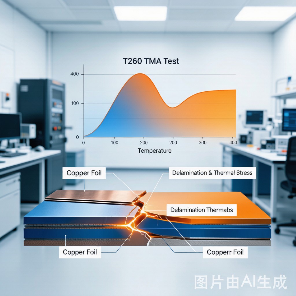
The Growing Delamination Problem in Lead-Free SMT
The transition to lead-free soldering has significantly increased the thermal stress experienced by PCB laminates during SMT assembly. SAC305 solder requires peak reflow temperatures of 245-260 degrees C—30-40 degrees C higher than the tin-lead eutectic (183 degrees C) used previously. At these elevated temperatures, the FR4 laminate is closer to its glass transition temperature (Tg), the copper-to-laminate adhesive bond weakens, and the risk of delamination and copper peel strength failure increases dramatically.
PCB delamination manifests in three forms: measling (white spots indicating micro-debonding within the laminate), blistering (localized swelling from trapped moisture vapor pressure), and full delamination (complete separation of copper layers from the laminate substrate). Each form has distinct root causes and prevention strategies, but all share a common consequence: compromised electrical integrity and mechanical reliability of the PCB assembly.
Delamination Mechanisms and Classification
Type 1: Measling (Micro-Delamination)
Measling appears as discrete white spots or cross-pattern marks visible through the solder mask, typically at glass fiber-resin interfaces within the laminate. The mechanism is differential thermal expansion between the glass fiber (CTE ~5 ppm/degrees C) and the epoxy resin (CTE ~50-70 ppm/degrees C below Tg, 150-200 ppm/degrees C above Tg) during reflow. At lead-free reflow temperatures (245-260 degrees C), the epoxy is above or near its Tg, and the 10-40x CTE differential creates interfacial stress that debonds the glass-resin interface at isolated points.
Measling is generally a cosmetic concern for Class 1 and Class 2 products (IPC-A-610 acceptance) but is a process indicator that the laminate is being stressed near its thermal limits. For Class 3 products (high-reliability), measling is a defect requiring investigation.
Type 2: Blistering (Moisture-Driven Delamination)
Blistering is the most common delamination mode in lead-free SMT assembly. The FR4 laminate absorbs moisture from ambient humidity during storage—at 50% RH and 25 degrees C, a 1.6 mm FR4 board absorbs 0.3-0.5% moisture by weight over 48 hours. During reflow at 245-260 degrees C, the trapped moisture vaporizes, generating internal vapor pressure that can reach 5-15 MPa in localized areas. When this pressure exceeds the interlaminar bond strength of the FR4 (typically 3-8 MPa at reflow temperature), the laminate separates, forming a visible blister.
Blistering typically occurs at the interface between the copper foil and the prepreg layer, where the bond strength is lowest at elevated temperature. The vapor pressure threshold for blister formation decreases with increasing temperature—at 260 degrees C, the threshold is approximately 40% lower than at 220 degrees C, making lead-free reflow significantly more susceptible to moisture-driven blistering.
Type 3: Full Delamination (Copper-Laminate Separation)
Full delamination is the complete separation of a copper layer (foil or i
er plane) from the laminate substrate. This is the most severe form and renders the PCB unusable. Full delamination occurs when the combined stress from thermal expansion mismatch, moisture vapor pressure, and mechanical stress exceeds the copper-to-laminate peel strength at reflow temperature.
At room temperature, copper peel strength on standard FR4 is 1.5-3.0 N/mm (per IPC-TM-650 2.4.8). At 260 degrees C, this drops to 0.3-0.8 N/mm—a 60-80% reduction. Any additional stress from moisture vapor pressure or CTE mismatch can push the effective stress above this reduced peel strength, causing full delamination.
Thermal Stress Testing Standards
T260 and T288 Testing (IPC-TM-650 2.4.24.1)
T260 and T288 tests measure the time-to-delamination of a PCB laminate sample at a fixed elevated temperature. The sample (25 x 25 mm) is placed in a TMA (Thermomechanical Analyzer) and heated to 260 degrees C (T260) or 288 degrees C (T288), then held at that temperature until delamination is detected by a thickness change.
| Laminate Type | Tg (degrees C) | T260 (min) | T288 (min) | Suitable For |
|---|---|---|---|---|
| Standard FR4 (Tg 140) | 135-145 | 5-15 | < 2 | Tin-lead reflow only |
| High-Tg FR4 (Tg 170) | 170-180 | 20-40 | 5-10 | Single lead-free reflow |
| Mid-loss FR4 (Tg 180) | 180-190 | 30-50 | 10-20 | Double lead-free reflow |
| High-Tg low-CTE (Tg 200+) | 200-220 | > 60 | > 30 | Multiple lead-free reflow + rework |
| Polyimide | 250-260 | > 60 | > 60 | Aerospace/military |
Copper Peel Strength Testing (IPC-TM-650 2.4.8)
Copper peel strength is measured by peeling a 3 mm wide strip of copper foil from the laminate at a 90-degree angle at a constant rate of 50 mm/min. The test is performed at room temperature and, for lead-free qualification, also at 260 degrees C using a heated fixture. Minimum acceptance criteria per IPC-4101:
- Room temperature: >= 1.0 N/mm (Class 2), >= 1.4 N/mm (Class 3)
- After thermal stress (260 degrees C, 10s): >= 0.8 N/mm (Class 2), >= 1.0 N/mm (Class 3)
- After 4x reflow at 260 degrees C: >= 0.6 N/mm (all classes—verifies resistance to repeated thermal cycling)
Root Causes of Delamination in Lead-Free Assembly
1. Moisture Absorption
Moisture absorption is the single most common cause of delamination in lead-free SMT. FR4 laminate absorbs moisture through the epoxy resin matrix and along the glass fiber-resin interface. The absorption rate follows Fick’s law—diffusion is faster at higher temperature and humidity:
- 0.3% weight gain in 48 hours at 25 degrees C / 50% RH
- 0.5% weight gain in 24 hours at 30 degrees C / 80% RH (typical Southeast Asian warehouse)
- 0.8% weight gain in 12 hours at 35 degrees C / 85% RH
The critical moisture threshold for blistering at 260 degrees C reflow is approximately 0.3-0.4% by weight. Boards stored in uncontrolled Southeast Asian environments exceed this threshold within 24 hours.
2. Insufficient Laminate Tg
If the laminate Tg is too close to the reflow temperature, the epoxy resin softens dramatically during reflow, losing its mechanical grip on the copper foil and glass fibers. A laminate with Tg 140 degrees C (standard FR4) operating at 260 degrees C reflow is 120 degrees C above Tg—well into the rubbery region where the resin modulus drops by 2-3 orders of magnitude. This makes the laminate extremely vulnerable to delamination from any mechanical or vapor pressure stress.
Requirement for lead-free assembly: Use laminate with Tg >= 170 degrees C (High-Tg FR4) for single reflow, and Tg >= 180 degrees C for double-sided reflow or rework scenarios.
3. CTE Mismatch Stress
Copper has a CTE of 17 ppm/degrees C, while FR4 has an in-plane CTE of 14-16 ppm/degrees C (below Tg) and a z-axis CTE of 50-70 ppm/degrees C (below Tg, increasing to 150-200 ppm/degrees C above Tg). During reflow, the z-axis expansion of the laminate is 3-10 times greater than the copper expansion, creating tensile stress at the copper-laminate interface. For thick boards (>2.4 mm) with many copper layers, the cumulative z-axis expansion can reach 0.1-0.2 mm, generating sufficient stress to delaminate copper planes.
4. Inadequate Copper Surface Treatment
The copper foil surface treatment at the laminate factory determines the mechanical bond between copper and resin. Standard treatments include:
- Red oxide treatment: Forms a rough copper oxide layer that mechanically interlocks with the resin during lamination. Provides good peel strength (2.0-3.0 N/mm) but can degrade at temperatures above 240 degrees C.
- Black oxide treatment: A thicker, more developed oxide layer with superior mechanical interlocking. Peel strength 2.5-3.5 N/mm. More resistant to thermal stress than red oxide.
- Treated foil (DTF – Double Treated Foil): Electrodeposited copper with nodular surface texture. Provides both mechanical interlocking and chemical bonding. Peel strength 2.0-3.0 N/mm with better high-temperature retention.
- Silane coupling agent: Chemical treatment that forms covalent bonds between copper and epoxy. Improves peel strength by 20-30% at reflow temperatures compared to oxide-only treatment.
Prevention Strategies
Bake-Out Before Assembly
Remove absorbed moisture by baking bare PCBs before SMT assembly. The standard bake-out is 125 degrees C for 4-24 hours (depending on board thickness and moisture level). For 1.6 mm boards stored at 50% RH:
- 4 hours at 125 degrees C: Removes 60-70% of absorbed moisture
- 8 hours at 125 degrees C: Removes 85-90%
- 24 hours at 125 degrees C: Removes > 95% (recommended for boards stored > 48 hours in uncontrolled environment)
After baking, assembly must begin within 8 hours (at 50% RH) to prevent re-absorption. Alternatively, re-seal baked boards in moisture-barrier bags with desiccant per J-STD-033.
MSL Management per J-STD-033
Classify bare PCBs by Moisture Sensitivity Level (MSL) and manage them accordingly:
- MSL 3: Maximum 168 hours floor life at <= 30 degrees C / 60% RH. Requires baking if exceeded.
- MSL 4: Maximum 72 hours floor life. More restrictive—common for thin boards (< 1.0 mm).
- MSL 5: Maximum 48 hours floor life. Very restrictive—used for ultra-thin boards or high-reliability applications.
Store bare PCBs in vacuum-sealed moisture-barrier bags with HIC (Humidity Indicator Card) and desiccant. If the HIC indicates moisture exposure, bake the boards before opening the bag.
Laminate Selection
Select laminate materials appropriate for the lead-free reflow profile and reliability requirements:
- Single reflow, standard reliability: High-Tg FR4 (Tg >= 170 degrees C, T260 >= 30 min, T288 >= 5 min)
- Double reflow or rework: Mid-loss FR4 (Tg >= 180 degrees C, T260 >= 40 min, T288 >= 10 min)
- Multiple reflow + rework + high reliability: Low-CTE laminate (Tg >= 200 degrees C, T260 >= 60 min, T288 >= 30 min, z-axis CTE < 100 ppm/degrees C above Tg)
- Extreme thermal stress: Polyimide or high-frequency laminates (PTFE/ceramic) with Tg > 250 degrees C
Reflow Profile Optimization
Minimize thermal stress by optimizing the reflow profile:
- Preheat ramp: 1-2 degrees C/second from ambient to 150 degrees C. Rapid preheating creates thermal gradients that stress the laminate.
- Soak zone: Hold at 150-200 degrees C for 60-120 seconds. This allows the board to reach thermal equilibrium and helps volatilize residual moisture without generating vapor pressure spikes.
- Reflow ramp: 1.5-3 degrees C/second from 200 to 245-255 degrees C. Avoid ramp rates above 3 degrees C/second above 200 degrees C.
- Time above liquidus: 60-90 seconds at peak 245-255 degrees C. Longer dwell increases delamination risk.
- Cooling rate: 1-4 degrees C/second. Rapid cooling creates thermal shock; use controlled cooling with moderate conveyor speed and ambient airflow.
Design Rules for Delamination Prevention
- Copper balance: Maintain balanced copper distribution on all layers. Large copper pour imbalances between layers create differential thermal expansion that delaminates the board during reflow. Aim for <20% copper area difference between adjacent layers.
- Thermal relief on large copper pours: Co
ect component pads to large copper pours with thermal relief spokes (2-4 spokes, 0.25 mm width) to prevent localized heat sinking that creates thermal gradients during reflow.
- Board thickness vs. layer count: Thicker boards with more layers have greater z-axis expansion and higher delamination risk. For 8+ layer boards, use low-CTE laminate (z-axis CTE < 100 ppm/degrees C above Tg).
- Avoid large unfilled via fields: Large arrays of unfilled vias create local weakness in the laminate. Fill critical vias with conductive or non-conductive fill material and plate them over (VIPPO – Via-in-Pad Plated Over) to restore laminate integrity.
Conclusion
PCB delamination and copper peel strength failure are the most significant reliability risks introduced by lead-free SMT assembly. The elevated reflow temperatures (245-260 degrees C) push standard FR4 laminates beyond their design limits, activating failure mechanisms—moisture vapor pressure blistering, CTE mismatch stress, and copper-laminate bond degradation—that were manageable at tin-lead reflow temperatures. Prevention requires a multi-layered approach: select laminate with adequate Tg and T260/T288 performance for the intended thermal profile, bake out moisture before assembly, manage MSL floor life per J-STD-033, optimize the reflow profile to minimize thermal stress, and design for balanced copper distribution and thermal relief. For manufacturers in Southeast Asia, where high ambient humidity accelerates moisture absorption, aggressive moisture management (vacuum packaging, nitrogen storage, pre-assembly baking) is particularly critical. By treating delamination prevention as a system-level design and process engineering challenge rather than a single-point fix, SMT manufacturers can achieve lead-free assembly reliability comparable to or exceeding the legacy tin-lead process.



