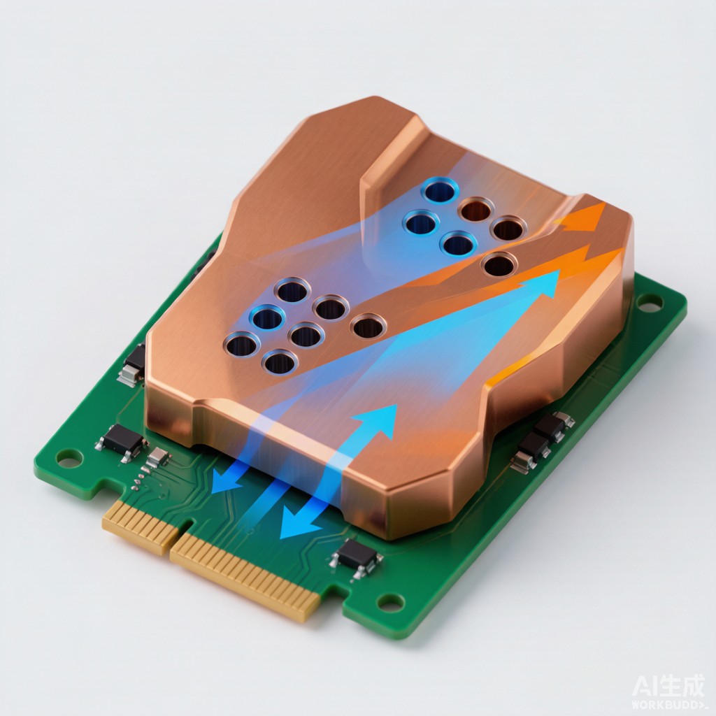
Introduction: Why Copper Strip Becomes a Heat Spreader
As power densities rise in motor drives, LED power supplies, battery management systems and industrial automation controllers, the PCB itself increasingly becomes the primary thermal path. A localized hot spot under a MOSFET, IGBT or LED driver can exceed 125°C while the rest of the board remains near ambient, creating reliability risks and premature failure. SMT copper strip, in the form of thin planar foil or etched bus-bar inserts, offers a simple and cost-effective way to spread heat laterally across the PCB before it is dumped into a heatsink, chassis or airflow path.
Unlike dedicated metal-core PCBs or expensive vapor chambers, copper strip heat spreaders can be added to standard FR-4 boards with minimal process change. They leverage copper’s exceptional thermal conductivity — roughly 400 W/m·K for pure copper, more than 1,000 times higher than FR-4 — to redistribute heat from a small junction area to a much larger board region. This article explains the engineering principles, sizing methods, attachment options and integration rules for SMT copper strip heat spreaders.
Thermal Conductivity and Spreading Resistance Basics
Why Lateral Spreading Matters
Heat leaves a component through a small footprint — perhaps a 5 mm × 5 mm thermal pad or several drain pads totaling 20 mm². If this heat must travel vertically through a thin PCB and then into the ambient, the thermal resistance is dominated by convection and interface resistance. But if the heat can first spread laterally over a 50 mm × 50 mm copper plane, the effective heat-transfer area increases by roughly 100 times, dramatically lowering junction temperature.
The lateral thermal resistance of a copper spreader is approximated by:
R_spread ≈ L / (k × A × t)
where L is the heat flow length, k is thermal conductivity, A is the conduction cross-section and t is copper thickness. For a 0.5 mm thick copper strip carrying heat 25 mm laterally with a 20 mm width, R_spread is only about 0.006 K/W — negligible compared to typical junction-to-case and interface resistances.
Material Choices: Bare Copper vs Alloyed Strip
For thermal management, pure copper C11000 or C10200 strip is preferred because alloying elements reduce conductivity. A comparison of common strip materials:
| Material | Thermal Conductivity (W/m·K) | Tensile Strength (MPa) | Best Use |
|---|---|---|---|
| C11000 ETP Copper | 388 | 220-250 | General heat spreaders, cost-sensitive |
| C10200 OFHC Copper | 391 | 220-250 | High-reliability, vacuum/brazing |
| C19400 Cu-Fe-P | 260 | 350-450 | Lead frames needing higher strength |
| C26800 Brass | 120 | 300-400 | Mechanical brackets, not primary spreaders |
For maximum heat spreading, specify a
ealed C11000 strip 0.3-1.0 mm thick. Thicker strip improves conductivity but increases weight, cost and board bowing risk.
SMT Copper Strip Heat Spreader Design Rules
Footprint and Aspect Ratio
Effective spreading requires the heat spreader to be significantly larger than the heat source. A practical rule of thumb is that the spreader footprint should extend at least 3-5 times the characteristic dimension of the hot component in each direction. For a 5 mm × 5 mm QFN thermal pad, this means a 25 mm × 25 mm copper island is a good starting point.
The aspect ratio of the spreader also matters. Long, narrow strips spread heat poorly in the transverse direction. Aim for a length-to-width ratio below 4:1 for any single copper island. If the board layout forces a narrow path, use multiple parallel copper strips or add cross ties to improve lateral conductivity.
Thickness Selection
Copper strip thickness for SMT heat spreaders typically ranges from 0.2 mm to 1.0 mm. The trade-offs are:
| Thickness | Thermal Performance | Process Compatibility | Typical Application |
|---|---|---|---|
| 0.2-0.3 mm | Moderate spreading | Compatible with standard SMT reflow | Low-power LED drivers, sensors |
| 0.5 mm | Good spreading | Requires stronger reflow profile | Motor drives, DC-DC converters |
| 0.8-1.0 mm | Excellent spreading | May need selective solder or mechanical fixation | High-current power modules, inverters |
For most medium-power applications, 0.5 mm copper strip provides the best balance between thermal performance and SMT process compatibility.
Attachment and Interface Resistance
Solder Attachment
Soldering the copper strip directly to exposed copper pads on the PCB provides the lowest thermal resistance, typically 0.5-2 K·mm²/W depending on solder alloy and thickness. SAC305 solder paste printed at 100-150 μm thickness after reflow gives reliable attachment. The strip should have a solderable finish such as immersion tin, OSP or matte Sn to ensure good wetting.
For large copper areas, voiding can reduce effective contact area. Use a window-pane stencil pattern with multiple small apertures rather than one large opening to promote outgassing and reduce voids. Target void area below 25% per thermal pad.
Thermal Adhesive and Gap Filler
When solder reflow of a heavy copper strip is impractical, thermally conductive adhesive provides a simpler assembly path. Acrylic or silicone adhesives with aluminum oxide or boron nitride filler offer thermal conductivity of 1.5-3.5 W/m·K. The resulting interface resistance is higher than solder — typically 5-15 K·mm²/W — but adequate for many applications.
Apply adhesive in a controlled thickness of 0.1-0.2 mm. Excessive thickness increases resistance; insufficient thickness causes air gaps. Use a fixture or spacer during cure to maintain bond-line uniformity.
Mechanical Clamping
For field-replaceable modules or very thick copper strips, mechanical clamping with screws or spring clips may be used. This requires a flat, clean interface and a thin layer of thermal grease or phase-change material. While convenient for service, clamped interfaces generally have higher and more variable resistance than soldered joints.
Integration with Thermal Vias and Heatsinks
Thermal Via Arrays
Copper strip heat spreaders on the top layer work best when paired with thermal via arrays that move heat to internal or bottom-layer copper planes. A typical via array under a power pad uses 0.3 mm diameter vias on a 1.0-1.2 mm pitch, plated to 25 μm copper thickness. The via array thermal resistance is roughly:
R_via_array ≈ t_plate / (N × k_cu × A_via_barrel)
For 20 vias, 1.6 mm board thickness and 25 μm plating, R_via_array is approximately 2-4 K/W — low enough that the via array rarely dominates the thermal path.
Transition to External Heatsinks
The final heat rejection step usually involves an external heatsink or the metal enclosure. Copper strip spreaders can terminate at board edges or co
ector regions where a thermal interface pad contacts the chassis. In sealed industrial enclosures, the spreader may dump heat into the enclosure walls, which then radiate and convect to ambient.
For high-power designs, consider using the copper strip as a direct mounting surface for a small aluminum heatsink. The aluminum provides low-cost fins and structure while the copper strip distributes heat evenly across the heatsink base, preventing localized hot fins.
Design Example: 100 W Motor Drive Inverter
Consider a three-phase motor drive with six MOSFETs in DPAK packages, each dissipating 4-5 W. A continuous 0.5 mm SMT copper strip, 60 mm × 40 mm, is soldered across the drain pads. Thermal vias transfer heat to a bottom-layer copper pour, and the assembly is mounted against an aluminum housing through a 1.5 W/m·K thermal pad.
Simulation results for this configuration show peak junction temperature reduced from 148°C to 108°C at 45°C ambient — a 40°C improvement that translates directly into longer capacitor life, lower Rdson drift and higher reliability margins. The incremental cost of the copper strip is small compared to upgrading to a larger heatsink or switching to ceramic substrate.
Conclusion
SMT copper strip heat spreaders are a practical, low-cost thermal management technique for high-power PCBs. By selecting the right copper alloy, thickness and footprint, and by integrating the strip with solder attachment, thermal vias and external heatsinks, engineers can significantly reduce hot-spot temperatures without redesigning the entire board. For Southeast Asian electronics manufacturers serving industrial, automotive and LED lighting markets, copper strip spreaders offer a mature supply chain and straightforward SMT integration that supports both performance and cost targets.



