Introduction: Why PBT-GF30 Dominates SMT Co
ector Insulator Design
Polybutylene terephthalate reinforced with 30% glass fiber (PBT-GF30) has emerged as the preferred modified plastic for surface-mount technology (SMT) co
ector insulator housings across Southeast Asian electronics manufacturing. The material’s combination of high dimensional stability, excellent electrical insulation properties, and superior mold flow characteristics makes it uniquely suited for the tight tolerance requirements of modern co
ector designs — where pin-to-pin spacing below 0.4 mm demands insulator wall thickness control within ±0.02 mm.
This article examines the engineering fundamentals behind PBT-GF30’s performance, comparing it with unfilled PBT and alternative modified plastics, and provides practical guidance for injection molding process optimization in tropical climate conditions.
PBT-GF30 Material Properties and Glass Fiber Reinforcement Mechanics
Base Polymer vs Reinforced Composite Properties
Unfilled PBT (polybutylene terephthalate) offers good electrical properties but suffers from relatively high mold shrinkage (1.9–2.2%) and low heat distortion temperature (HDT of 60°C at 1.8 MPa). The addition of 30% short glass fiber (typically E-glass, 3–4.5 mm initial length, reduced to 0.2–0.5 mm after compounding shear) transforms these properties dramatically:
| Property | Unfilled PBT | PBT-GF30 | Unit |
|---|---|---|---|
| Mold Shrinkage (parallel) | 1.9–2.2 | 0.2–0.4 | % |
| Mold Shrinkage (transverse) | 2.0–2.5 | 0.8–1.2 | % |
| HDT @ 1.8 MPa | 60 | 205 | °C |
| Tensile Strength | 55 | 140 | MPa |
| Flexural Modulus | 2,400 | 9,500 | MPa |
| Moisture Absorption (24h) | 0.25 | 0.15 | % |
| CTE (parallel) | 90 | 25 | ×10⁻⁶/°C |
| CTE (transverse) | 120 | 55 | ×10⁻⁶/°C |
| Volume Resistivity | 10¹⁵ | 10¹⁵ | Ω·cm |
| Dielectric Strength | 30 | 35 | kV/mm |
The anisotropic shrinkage behavior — low in the flow direction (0.2–0.4%) but higher transversely (0.8–1.2%) — is a critical design consideration for co
ector housings where wall sections orient in different directions relative to the gate.
Glass Fiber Orientation and Dimensional Effects
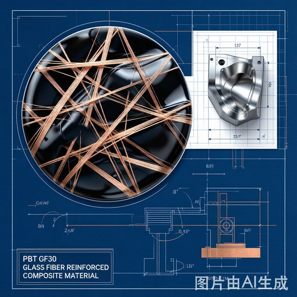
During mold filling, glass fibers align preferentially along the flow direction near the cavity wall (skin layer) and exhibit random orientation in the core. This orientation gradient produces the anisotropic shrinkage pattern. For a co
ector housing with a center gate, the long walls (parallel to flow) shrink less than the end walls (transverse), requiring mold cavity dimension compensation of +0.3% (parallel) vs +1.0% (transverse) to achieve net-zero dimensional deviation.
Mold Flow Analysis for Thin-Wall Co
ector Housing
Flow Length and Gate Design
PBT-GF30 exhibits moderate flowability compared to unfilled PBT. The melt flow index (MFI) typically ranges from 15–25 g/10 min (at 250°C/2.16 kg). For a 0.5 mm wall thickness co
ector housing, the maximum flow length at standard injection pressure (80 MPa) is approximately 60–80 mm — sufficient for most SMT co
ector designs (0.5–2.0 mm pitch, 6–30 positions).
Gate selection critically affects fiber orientation and dimensional outcome:
– Center edge gate: Produces bidirectional flow, balanced fiber orientation, moderate anisotropy. Best for rectangular housings.
– Pin gate (sub-gate): Automatic degating, single-point flow, strong directional fiber orientation. Suitable for small single-row co
ectors.
– Film gate: Uniform flow across width, minimized warpage, but requires manual degating. Preferred for high-precision multi-row housings.
MoldFlow Simulation Parameters
For accurate PBT-GF30 mold flow simulation using Moldex3D or Moldflow:
– Melt temperature: 240–260°C (optimal 250°C)
– Mold temperature: 80–100°C (critical: higher mold temp reduces differential shrinkage)
– Injection speed: Medium-to-fast (50–80 mm/s) to maintain fiber orientation uniformity
– Holding pressure: 60–80 MPa for 2–4 seconds (overpacking reduces post-mold shrinkage)
– Cooling time: 8–15 seconds depending on wall thickness
Moisture Absorption and Tropical Climate Dimensional Effects
Hygroscopic Expansion in Southeast Asian Environments
Although PBT-GF30’s moisture absorption rate (0.15% at 24h, equilibrium ~0.35% at 50% RH) is relatively low compared to nylon-based modified plastics, the dimensional impact in Southeast Asian conditions (RH 80–95%, temperatures 30–40°C) is measurable and must be accounted for:
– Equilibrium moisture content at 85% RH/35°C: approximately 0.45% (vs 0.35% at standard 50% RH)
– Linear expansion per 0.1% moisture gain: approximately 0.02% (based on PBT’s hygroscopic expansion coefficient)
– Net dimensional shift at tropical equilibrium: +0.04% to +0.09% linear
For a 0.4 mm pitch co
ector insulator with 10 mm overall length, this equates to 4–9 μm dimensional shift — potentially exceeding the ±20 μm tolerance window if mold design does not pre-compensate.
Drying Requirements and Process Window
PBT-GF30 plastic pellets must be dried before molding to prevent surface splay and internal voids:
– Recommended drying: 120–130°C for 3–4 hours (desiccant dryer, dew point ≤−30°C)
– Maximum acceptable moisture content before molding: ≤0.03%
– Re-drying after 2+ hours hopper exposure in humid conditions
In Southeast Asian factories, hopper drying systems with inline dehumidifiers are essential rather than optional, as ambient humidity can re-absorb moisture into pre-dried pellets within 30–60 minutes of hopper exposure.
Alternative Modified Plastic Comparison for Co
ector Applications
| Material | Mold Shrinkage (%) | HDT (°C) | Moisture 24h (%) | Cost Index | Best Application |
|---|---|---|---|---|---|
| PBT-GF30 | 0.3/1.0 | 205 | 0.15 | 1.0 | General SMT co
ectors, 0.4mm+ pitch |
| PBT-GF45 | 0.2/0.8 | 210 | 0.12 | 1.2 | High-precision co
ectors, 0.3mm pitch |
| LCP-GF30 | 0.1/0.3 | 280 | 0.02 | 3.5 | Ultra-fine pitch RF co
ectors, 0.25mm |
| PA66-GF30 | 0.5/1.5 | 255 | 1.0 | 0.7 | Automotive co
ectors (dry conditions only) |
| PPS-GF40 | 0.2/0.5 | 260 | 0.02 | 2.0 | High-temp industrial co
ectors |
PBT-GF30 remains the cost-performance leader for standard SMT co
ectors. Liquid crystal polymer (LCP) is superior for ultra-fine pitch but costs 3.5× more. Nylon PA66-GF30 is cheaper but unsuitable for humid environments due to high moisture absorption.
Processing Best Practices for Southeast Asian Manufacturing
Mold Temperature Control
Maintaining mold temperature at 90–100°C (rather than the minimum 80°C) significantly reduces differential shrinkage and warpage. Oil-based mold temperature controllers are recommended over water systems for PBT-GF30, as they can sustain the required temperature range more reliably.
Post-Mold A
ealing
For critical-tolerance co
ector housings, a controlled post-mold a
ealing cycle (150°C for 30 minutes, followed by slow cooling) eliminates residual internal stresses and stabilizes dimensions within ±0.01% — essential for 0.3 mm pitch and below.
Quality Inspection Protocol
Dimensional inspection of PBT-GF30 co
ector housings should include:
– CMM measurement within 2 hours of molding (before moisture equilibration)
– Optical measurement of pin pocket dimensions (±0.02 mm tolerance)
– Visual inspection for fiber exposure at contact surfaces (prohibited per IEC 60335-1)
– Batch moisture content verification via gravimetric method (target ≤0.05%)
Conclusion
PBT-GF30 modified plastic pellets provide an optimal balance of dimensional stability, mold flow performance, and cost-effectiveness for SMT co
ector insulator housings in Southeast Asian electronics manufacturing. Understanding the anisotropic shrinkage behavior, moisture absorption dynamics, and fiber orientation effects enables mold designers and process engineers to achieve the tight tolerances required by modern fine-pitch co
ectors. Proper drying protocols, mold temperature control, and post-mold a
ealing further ensure consistent production quality in tropical climate conditions.



