Introduction: The Contact Finish Determines Co
ector Lifetime
The electroplated finish on an SMT co
ector contact pin is only 0.5–5.0 μm thick — roughly the diameter of a red blood cell — yet it governs every aspect of co
ector performance: insertion force, wear life, corrosion resistance, solderability, and long-term electrical contact stability. For high-reliability applications (automotive under-hood, aerospace, medical devices, industrial automation), the contact finish must survive 100–500 mating cycles, 1,000+ hours of mixed flowing gas corrosion testing, and 3,000+ thermal cycles without exceeding a 10 mΩ contact resistance increase.
Hard gold (gold-cobalt or gold-nickel alloy, 99.7% Au + 0.3% Co/Ni hardener) has been the industry-standard co
ector contact finish for decades. Palladium-nickel alloy (80Pd-20Ni) has emerged as a compelling alternative — offering higher hardness, lower porosity at equivalent thickness, and freedom from the nickel diffusion and intermetallic reliability concerns that plague thin gold deposits. This article provides an engineering comparison of these two finishes for SMT co
ector contact applications.
Plating Layer Architecture: Understanding the Full Stack
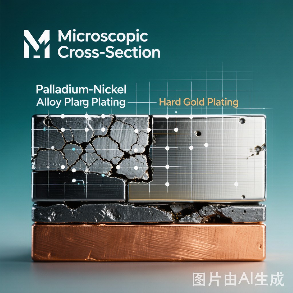
Hard Gold Finish Stack
A typical hard gold contact finish is not a single layer but a three-layer stack electroplated onto the copper alloy substrate (typically phosphor bronze C51000 or brass C26800):
- Nickel underplate (1.25–2.5 μm): Diffusion barrier — prevents copper from the substrate from diffusing through the gold layer to the surface, where it oxidizes to form a high-resistance Cu₂O/CuO film. Sulfamate nickel (low stress, 3–50 MPa tensile) is preferred over Watts nickel (high stress, 120–250 MPa).
- Hard gold layer (0.75–2.5 μm): The functional contact surface — Au-Co (0.2–0.3% Co) or Au-Ni (0.2–0.5% Ni) alloy with Knoop hardness 130–200 HK₂₅, achieved through co-deposited hardener atoms that pin grain boundaries and impede dislocation motion.
- Gold flash / cobalt oxide surface film (10–50 nm): The outermost surface — a thin lubricating cobalt oxide layer that reduces friction coefficient from μ=0.8 (pure gold, severe galling) to μ=0.3–0.5 (hard gold, acceptable for co
ector applications).
Palladium-Nickel Finish Stack
Palladium-nickel (80Pd-20Ni) offers a fundamentally simpler architecture:
- Nickel underplate (1.25–2.5 μm): Same function as gold stack — copper diffusion barrier.
- Palladium-nickel alloy layer (0.75–2.5 μm): The functional contact surface — 80 wt% Pd + 20 wt% Ni, electrodeposited from a bath containing palladium as Pd(NH₃)₄²⁺ and nickel as Ni(NH₃)₆²⁺. Knoop hardness 350–450 HK₂₅ — approximately 2–3× harder than hard gold.
- Optional gold flash (0.05–0.15 μm): Thin gold top layer for solderability and corrosion protection during storage. Not required for contact function — Pd-Ni is sufficiently noble (standard electrode potential Pd²⁺/Pd = +0.92 V SHE vs Au³⁺/Au = +1.50 V SHE) to resist atmospheric corrosion.
Porosity: The Hidden Reliability Killer
Porosity Mechanism and Measurement
Electroplated deposits are never truly continuous at thin thicknesses. Microscopic pores — caused by substrate surface roughness, plating bath contamination (particulates, organic residues), hydrogen bubble entrapment during deposition, and crystallographic growth defects — penetrate through the plating to the nickel underplate or copper substrate. In corrosive environments (industrial atmospheres containing H₂S, SO₂, Cl₂, NOₓ — per ASTM B845 mixed flowing gas test), these pores become galvanic corrosion sites.
Porosity is measured by the nitric acid vapor test (ASTM B735) or the SO₂ fuming test (ASTM B799), which attacks nickel or copper exposed at pore bottoms and produces colored corrosion products visible under 10× magnification. Porosity is reported as pores/cm² — a 1 cm² contact area with 5 pores has a 5 pores/cm² rating.
Comparative Porosity vs Thickness
| Plating Thickness (μm) | Hard Gold Porosity (pores/cm²) | Pd-Ni Porosity (pores/cm²) | Pd-Ni Advantage |
|---|---|---|---|
| 0.5 | 15–30 | 3–8 | 3–5× lower |
| 0.75 | 8–15 | 1–4 | 3–5× lower |
| 1.0 | 3–8 | 0.5–2 | 3–6× lower |
| 1.5 | 1–3 | 0.1–0.5 | 5–10× lower |
| 2.0 | 0.3–1 | <0.1 | — (both nearly pore-free) |
| 2.5 | 0.1–0.3 | <0.05 | — |
Pd-Ni electrodeposits achieve pore-free coverage at approximately half the thickness of hard gold — a decisive advantage when minimizing precious metal usage. The finer grain structure of Pd-Ni (grain size 10–50 nm) compared to hard gold (50–200 nm) creates a denser deposit with fewer through-thickness defects. For a 1.0 μm Pd-Ni finish, the corrosion performance (per ASTM B845 MFG Class II, 10-day exposure) is equivalent to a 2.0 μm hard gold finish.
Wear Resistance and Durability
Contact Wear Mechanisms
Co
ector contact wear occurs through a combination of adhesive wear (cold welding of asperity contacts followed by tearing — the dominant mechanism for soft pure gold), abrasive wear (hard particles or work-hardened debris plowing the surface — dominates for hard gold and Pd-Ni), and fretting (micro-amplitude oscillatory motion, 5–50 μm, driven by vibration and thermal expansion).
Comparative Wear Performance
| Wear Parameter | Hard Gold (Au-Co 0.3%) | Pd-Ni (80Pd-20Ni) | Significance |
|---|---|---|---|
| Knoop Hardness (HK₂₅) | 130–200 | 350–450 | Pd-Ni is 2–3× harder → lower abrasive wear rate |
| Friction Coefficient (μ, dry, vs same metal) | 0.3–0.5 | 0.4–0.6 | Hard gold is slightly lower friction |
| Wear Track Depth after 200 cycles (μm) | 0.8–2.0 | 0.3–0.8 | Pd-Ni wears 2–3× less |
| Cycles to 50% thickness loss (1.0 μm initial) | 200–400 | 500–1,000 | Pd-Ni: 2–3× longer wear life |
| Fretting Corrosion Resistance | Moderate (forms Au debris) | Good (Pd/Ni oxide is conductive) | Pd-Ni is better in vibration environments |
| Contact Resistance after 10⁴ fretting cycles (mΩ) | 5–50 (wide scatter) | 5–15 (tight distribution) | Pd-Ni: more stable fretting behavior |
The wear advantage of Pd-Ni comes from its higher hardness — harder surfaces resist abrasive wear by requiring more energy to plastically deform asperities. However, the slightly higher friction coefficient of Pd-Ni (0.4–0.6 vs 0.3–0.5) means that insertion force may be 10–20% higher for Pd-Ni contacts — a consideration for high-pin-count co
ectors (≥100 pins) where total insertion force is a design constraint.
Fretting corrosion is the critical differentiator for automotive and industrial co
ectors. When Au-Co wears through during fretting, the exposed nickel underplate oxidizes to NiO — a semiconducting oxide that creates high and unstable contact resistance (5–50 mΩ with wide variation). When Pd-Ni wears, the exposed nickel forms a thin, conductive mixed oxide that maintains contact resistance below 15 mΩ. This is Pd-Ni’s single most important reliability advantage over hard gold in vibration environments.
Intermetallic Compound (IMC) Growth and Diffusion Barrier Performance
Nickel Diffusion Through Gold: The Classic Failure Mode
At co
ector operating temperatures of 85–125°C (automotive under-hood, power electronics), nickel atoms from the underplate diffuse through the gold layer via grain boundary diffusion — a path that is 10⁴–10⁶ times faster than bulk lattice diffusion at these temperatures. When nickel reaches the gold surface, it oxidizes to NiO, creating a high-resistance film that increases contact resistance from 2–5 mΩ (clean gold) to 20–200 mΩ (failure threshold typically 10 mΩ increase).
The time to nickel diffusion failure follows an Arrhenius relationship:
- At 125°C: 1,000–3,000 hours for 0.75 μm Au; 3,000–8,000 hours for 1.5 μm Au
- At 85°C: 10,000–30,000 hours for 0.75 μm Au; 30,000–80,000 hours for 1.5 μm Au
For automotive under-hood co
ectors targeting 15-year/150,000-mile lifetime at 85–105°C continuous, a 1.5 μm minimum gold thickness is typically specified — at significant precious metal cost.
Pd-Ni as a Diffusion Barrier
Pd-Ni fundamentally solves this problem. Palladium has an extremely low self-diffusion coefficient and acts as an excellent diffusion barrier for nickel and copper. In Pd-Ni deposits, nickel is already present throughout the layer at 20 wt% — nickel diffusion through the layer is irrelevant because nickel is already at the surface. The contact resistance of Pd-Ni remains stable even after 5,000 hours at 125°C because no new insulating species appears on the surface. This makes Pd-Ni the preferred finish for high-temperature co
ector applications where gold’s nickel diffusion barrier limitations would force uneconomically thick gold deposits.
Cost Analysis: Gold Price Sensitivity
| Cost Element | Hard Gold (1.0 μm) | Pd-Ni (1.0 μm) | Pd-Ni (0.75 μm) + Au Flash |
|---|---|---|---|
| Material cost index (Au @ $2,000/oz, Pd @ $1,000/oz) | 1.0 | 0.25–0.35 | 0.30–0.40 |
| Material cost index (Au @ $2,500/oz, Pd @ $1,500/oz) | 1.0 | 0.35–0.45 | 0.40–0.50 |
| Plating bath chemistry cost | High | Moderate | Moderate |
| Bath maintenance complexity | Moderate | Higher (Pd bath control) | Higher |
At current precious metal prices, Pd-Ni (1.0 μm) costs 60–75% less in raw material than hard gold (1.0 μm) — primarily because palladium is 50% the price of gold per troy ounce, and Pd-Ni is 80% palladium by weight (i.e., only 0.8× the metal cost per unit volume). The gold flash variant (0.05–0.15 μm Au on top of 0.75 μm Pd-Ni) adds minimal cost while improving solderability for SMT assembly.
Selection Guide for SMT Co
ector Applications
| Application | Recommended Finish | Rationale |
|---|---|---|
| Consumer electronics (USB, HDMI, <100 cycles) | Hard gold, 0.75 μm | Lowest cost, adequate for benign environment, low cycles |
| Automotive under-hood (125°C, 100–300 cycles, vibration) | Pd-Ni, 1.0 μm | No nickel diffusion failure, superior fretting resistance |
| Industrial automation (vibration, 200–500 cycles) | Pd-Ni, 1.0 μm + Au flash | Fretting resistance + solderability, long wear life |
| Medical device co
ectors (sterilization cycles) |
Pd-Ni, 1.25 μm | Chemical resistance to sterilants, stable contact resistance |
| Telecom backplane (>500 cycles) | Pd-Ni, 1.5 μm | Maximum wear life for high-mating-cycle applications |
| Cost-sensitive consumer (audio jacks, battery contacts) | Hard gold, 0.5–0.75 μm | Lowest total cost, adequate for <50 cycles |
Conclusion
Palladium-nickel alloy (80Pd-20Ni) electroplating offers a technically superior alternative to hard gold for SMT co
ector contact finishes in applications where operating temperature exceeds 85°C, vibration-induced fretting is a reliability risk, or mating cycles exceed 200. Pd-Ni achieves pore-free corrosion protection at approximately half the thickness of hard gold, provides 2–3× longer wear life due to its higher hardness (350–450 vs 130–200 HK₂₅), and eliminates the nickel diffusion barrier failure mode that limits gold’s high-temperature reliability. At current precious metal prices, Pd-Ni is 60–75% less expensive in material cost than an equivalent-thickness hard gold deposit. For consumer electronics with benign operating conditions and low mating cycles, hard gold at 0.75 μm remains the cost-effective default. For automotive, industrial, and high-reliability electronics — where a single co
ector field failure costs orders of magnitude more than the plating — Pd-Ni is the engineering-superior choice.



