Introduction
While most EMI shielding discussions focus on high-frequency electromagnetic waves (above 30 MHz), low-frequency magnetic fields (50 Hz–100 kHz) pose a distinct and challenging interference source for sensitive SMT equipment. Power transformers, switching regulators, and induction heating systems generate intense low-frequency magnetic fields that can distort sensor signals, induce noise in precision measurement circuits, and interfere with magnetic storage devices. Mu-metal—a high-permeability nickel-iron alloy—is the premier material for attenuating these fields, but its selection and application require careful engineering.
Understanding Low-Frequency Magnetic Shielding
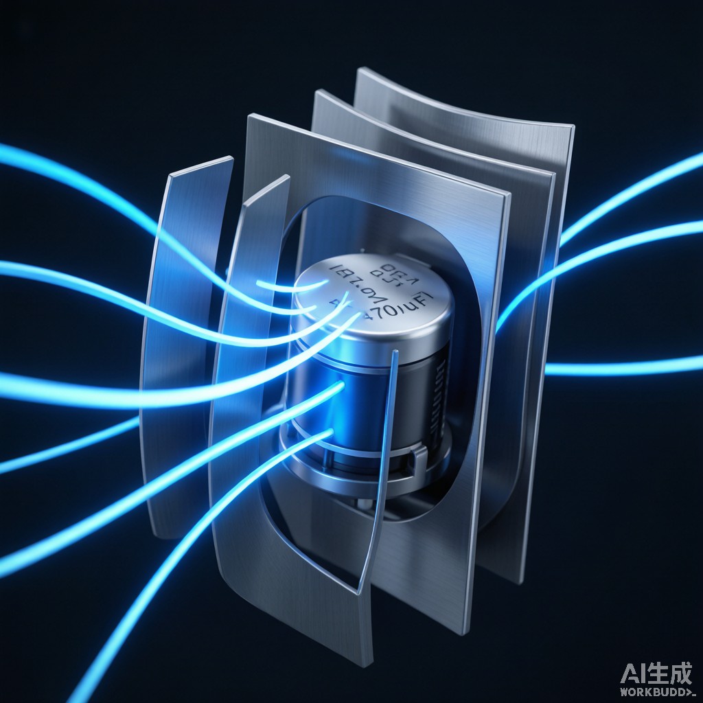
Unlike high-frequency EMI, which can be blocked by conductive materials through reflection and absorption (skin effect), low-frequency magnetic fields require a different mechanism: flux redirection. A high-permeability material provides a low-reluctance path that diverts magnetic flux lines around the protected volume.
The shielding effectiveness (SE) of a magnetic shield depends on the material’s permeability, thickness, and geometry:
SE (dB) = 20 × log₁₀(μr × t / D)
Where μr is relative permeability, t is shield thickness, and D is shield diameter. This formula illustrates why high permeability is critical—a material with μr = 50,000 provides 100× more attenuation than one with μr = 500 at the same thickness.
Mu-Metal Properties and Composition
Mu-metal is a soft ferromagnetic alloy with the following typical composition:
| Element | Percentage |
|---|---|
| Nickel (Ni) | 80% |
| Iron (Fe) | 15% |
| Molybdenum (Mo) | 4.2% |
| Chromium (Cr) | 0.5% |
| Manganese (Mn) | 0.3% |
The key properties that make mu-metal ideal for low-frequency shielding include:
- Initial permeability (μi): 30,000–80,000 (vs. 200–5,000 for silicon steel)
- Maximum permeability (μm): 200,000–400,000
- Saturation flux density (Bs): 0.7–0.8 T (relatively low, requiring multi-layer design for strong fields)
- Coercivity (Hc): 1–4 A/m (very low, meaning minimal residual magnetism)
Mu-Metal vs Alternative Shielding Materials
| Material | μi | Bs (T) | SE at 50Hz (dB) | Cost Factor | Best Application |
|---|---|---|---|---|---|
| Mu-metal | 30,000–80,000 | 0.75 | 40–70 | 10× | Weak field, high attenuation |
| Grain-oriented silicon steel | 1,500–5,000 | 2.0 | 15–30 | 1× | Strong field, cost-sensitive |
| Permendur (Fe-Co-V) | 800–5,000 | 2.35 | 15–25 | 8× | Very strong field |
| Conductive copper | 1 | N/A | 2–5 | 0.5× | High-frequency only |
| Amorphous (Metglas) | 10,000–100,000 | 0.55 | 35–60 | 5× | Pulsed field, thin gauge |
Key Trade-Offs
Mu-metal excels at shielding weak to moderate magnetic fields but has a critical limitation: low saturation flux density (0.75 T). When exposed to strong fields (above 0.5 T), mu-metal saturates and loses its shielding effectiveness entirely. In such cases, a multi-layer shield design is required, with an outer layer of high-saturation material (silicon steel or carbon steel) to reduce the field before it reaches the i
er mu-metal layer.
Multi-Layer Shield Design for SMT Equipment
For SMT manufacturing equipment such as reflow ovens with large transformers, or precision test systems near power distribution panels, a multi-layer shield design is often necessary:
Three-Layer Shield Architecture
- Outer layer (conductive): 0.5–1.0mm copper or aluminum. Provides high-frequency reflection and eddy current attenuation. Handles the RF component of interference.
- Middle layer (high saturation): 1.0–2.0mm silicon steel or carbon steel. Absorbs the bulk of the low-frequency flux, reducing field strength before it reaches the mu-metal.
- I
er layer (high permeability)
: 0.5–1.0mm mu-metal. Provides the final attenuation of residual low-frequency fields, achieving the target SE specification.
A properly designed three-layer shield can achieve 60–80 dB attenuation at 50 Hz, compared to 40–70 dB for mu-metal alone and 15–30 dB for silicon steel alone.
Hydrogen A
ealing and Shape Sensitivity
Mu-metal requires a critical high-temperature hydrogen a
ealing process (1,100–1,200°C for 2–4 hours) after forming to develop its maximum permeability. Any mechanical deformation—including bending, cutting, or even rough handling—after a
ealing will degrade the magnetic properties significantly (μi can drop from 50,000 to below 5,000).
This shape sensitivity has important implications for SMT equipment shielding design:
- Shields must be designed as simple geometries (cylinders, flat panels, right-angle boxes) that can be formed before a
ealing
- Post-a
ealing modifications (drilling, cutting, welding) are prohibited; all mounting features must be designed in before the final a
eal
- Transportation and installation require careful handling to avoid impact or vibration damage
- Spot welding or mechanical clamping (not TIG welding) is used for assembly after a
ealing
Southeast Asian Manufacturing Considerations
For electronics manufacturers in Southeast Asia, several regional factors affect mu-metal shield design:
- Humidity and corrosion: Mu-metal is susceptible to corrosion in humid tropical environments. Nickel plating (2–5μm) or conformal coating is essential for long-term reliability.
- Power frequency: Most SE Asian countries use 50 Hz power, meaning shielding must be optimized for 50 Hz rather than 60 Hz fields. At 50 Hz, the field period is longer, requiring thicker shields for equivalent attenuation.
- Cost optimization: Mu-metal is expensive ($50–100/kg). Using hybrid designs (silicon steel outer + mu-metal i
er) can reduce material costs by 40–60% while maintaining target SE.
Shielding Effectiveness Measurement
Verification of low-frequency magnetic shielding effectiveness requires specialized test methods:
- Helmholtz coil method: Generates a uniform magnetic field at the test frequency. Field probes measure attenuation inside vs outside the shield.
- IEEE Std 1140: Standard method for measuring magnetic shielding effectiveness of planar materials.
- ASTM A698: Test method for magnetic shielding effectiveness of ferromagnetic materials.
Typical acceptance criteria for SMT equipment shielding range from 30 dB (general industrial) to 60 dB (precision measurement) to 80 dB (magnetic sensor calibration).
Conclusion
Mu-metal remains the highest-performance material for low-frequency magnetic EMI shielding in SMT equipment, offering permeability levels 10–100× greater than silicon steel. However, its low saturation flux density requires multi-layer shield designs when strong magnetic fields are present. The hydrogen a
ealing requirement and shape sensitivity demand careful design and handling. For Southeast Asian manufacturers, hybrid shield designs combining high-saturation outer layers with mu-metal i
er layers provide the optimal balance of performance and cost for protecting sensitive SMT equipment from low-frequency magnetic interference.



