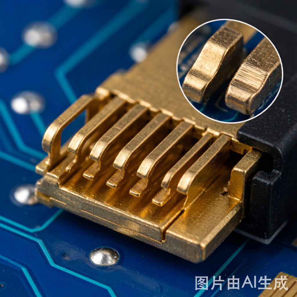
Introduction: Why Gold Plating Matters for SMT Edge Co
ectors
Gold plating on SMT edge card co
ector contacts serves a dual purpose: it provides a tarnish-free, low-contact-resistance surface that remains stable over decades of service, and it acts as a diffusion barrier preventing underlying nickel from migrating to the contact interface. However, not all gold plating is created equal. The choice between hard gold and soft gold dramatically impacts co
ector insertion cycle life, contact force retention, and long-term reliability—especially for applications requiring repeated mating cycles such as test fixtures, removable memory modules, and field-serviceable industrial electronics.
Hard Gold vs Soft Gold: Fundamental Differences
Composition and Hardness
Soft gold (Type I per ASTM B488) is essentially pure gold (>99.9% Au) deposited from cyanide-based baths. It exhibits a Knoop hardness of 40–90 HK₂₅, making it soft and ductile. Hard gold (Type II per ASTM B488) contains 0.1–0.2% cobalt or nickel co-deposited from acidic gold-cobalt or gold-nickel baths, achieving Knoop hardness of 130–200 HK₂₅—roughly 2–4× harder than soft gold.
| Property | Soft Gold (Type I) | Hard Gold (Type II) |
|---|---|---|
| Purity | >99.9% Au | 99.8% Au + 0.1–0.2% Co/Ni |
| Knoop Hardness (HK₂₅) | 40–90 | 130–200 |
| Density (g/cm³) | 19.3 | 17.5–18.0 |
| Grain Size | 2–5 μm | 0.05–0.2 μm (nanocrystalline) |
| Ductility | Excellent | Limited |
| Porosity | Low | Higher (requires thicker deposit) |
| Contact Resistance (mΩ) | 0.5–1.0 | 1.0–3.0 |
| Typical Thickness | 0.025–0.10 μm (flash) | 0.05–1.27 μm |
Contact Resistance Trade-off
The co-deposited cobalt or nickel in hard gold forms a thin oxide/hydroxide layer at the surface, slightly increasing initial contact resistance. Soft gold, being oxide-free, achieves the lowest possible contact resistance. For high-frequency signal applications (>1 GHz), soft gold is often preferred to minimize insertion loss. However, for general-purpose edge card co
ectors carrying digital signals below 500 MHz, the contact resistance difference is negligible in practice.
Insertion Cycle Wear Performance
The primary justification for hard gold is wear resistance during repeated co
ector mating cycles. Each insertion subjects the gold surface to frictional shear against the mating contact (typically phosphor bronze or beryllium copper with similar gold plating). The wear mechanism proceeds through three stages:
Stage 1: Break-in Wear (Cycles 1–50)
Initial mating cycles remove surface asperities and establish the true contact area. Soft gold deforms plastically under contact pressure (typically 50–100 g per contact), increasing the apparent contact area. This is beneficial for contact resistance but accelerates material removal. Hard gold resists deformation, maintaining a smaller but more stable contact zone.
Stage 2: Steady-State Wear (Cycles 50–500)
Material is gradually removed through adhesive and abrasive wear. Soft gold loses approximately 5–15 nm per cycle at typical contact pressures, while hard gold loses 1–3 nm per cycle. The wear rate depends on contact force, surface roughness, and the presence of contaminants.
Stage 3: Nickel Exposure (Failure Point)
Once the gold layer is perforated, the underlying nickel barrier is exposed. Nickel forms a passive oxide (NiO) within hours in ambient air, and contact resistance increases from 100 mΩ. The co
ector has effectively failed at this point, even though mechanical mating is still possible.
| Gold Type | Thickness | Cycles to Ni Exposure | Recommended Application |
|---|---|---|---|
| Soft gold flash | 0.05 μm | 10–25 | One-time assembly, wire bonding |
| Soft gold | 0.15 μm | 50–100 | Low-cycle co
ectors, test points |
| Hard gold | 0.38 μm | 250–500 | Standard edge card co
ectors |
| Hard gold | 0.76 μm | 500–1000 | Test sockets, industrial co
ectors |
| Hard gold | 1.27 μm | 1000–2500 | Military/aerospace, burn-in sockets |
ASTM B488 Classification System
ASTM B488 is the governing standard for electrodeposited gold plating on engineering substrates. It classifies gold deposits by type (purity/hardness), grade (thickness), and class (underplate requirements):
- Type I: 99.9%+ Au, minimum hardness (soft gold)
- Type II: 99.0%+ Au, 130–200 HK₂₅ (hard gold, Co-hardened)
- Type III: 99.0%+ Au, 90–130 HK₂₅ (medium hard, Ni-hardened)
- Grade A: 0.25 μm minimum
- Grade B: 0.75 μm minimum
- Grade C: 1.27 μm minimum
- Class 1: Nickel underplate required (2.5 μm minimum)
- Class 2: No underplate required
For a typical SMT edge card co
ector requiring 500+ insertion cycles, the specification should read: ASTM B488 Type II, Grade B, Class 1—hard gold at 0.75 μm minimum over 2.5 μm nickel underplate.
Nickel Underplate: The Unsung Hero
The nickel barrier layer beneath the gold is critical for two reasons. First, it prevents copper and zinc from the substrate brass from diffusing through the gold (gold is remarkably porous to copper at elevated temperatures). Without nickel, copper migration through thin gold occurs within months at 70°C, forming copper oxide at the surface and destroying contact resistance. Second, the nickel layer provides a hard, smooth substrate that supports the gold during contact wear, effectively extending the wear life by preventing substrate deformation.
Sulfamate nickel is preferred over Watts nickel for co
ector applications because of its lower internal stress (20–70 MPa vs. 120–250 MPa), reducing the risk of microcracking during thermal cycling. The recommended nickel thickness is 2.5–5.0 μm for edge card co
ectors, with 1.5 μm minimum for cost-optimized applications.
Environmental Durability Factors
Tribocorrosion in Humid Environments
In tropical climates with high humidity, the frictional wear process generates fresh gold surfaces that are immediately exposed to moisture. Soft gold, being more porous, allows moisture to reach the nickel underplate sooner, initiating corrosion at the gold-nickel interface. Hard gold’s denser nanocrystalline structure provides better moisture barrier performance, extending co
ector life in humid environments by 30–50%.
Fretting Corrosion
Fretting—small-amplitude oscillatory motion between mated contacts caused by vibration or thermal expansion—creates wear debris that oxidizes and accumulates at the contact interface. Hard gold generates finer, harder wear particles that are more easily displaced from the contact zone, while soft gold produces larger, softer particles that tend to compact and form insulating layers. For applications subject to vibration (automotive, industrial machinery), hard gold is strongly recommended.
Cost Considerations
Hard gold plating costs approximately 1.5–2× more than soft gold at equivalent thickness, due to the more complex bath chemistry and slower deposition rates. However, the cost difference is typically a small fraction of total co
ector cost. For a typical edge card co
ector with 0.75 μm hard gold over 2.5 μm nickel, the plating cost represents $0.02–0.05 per contact. Choosing soft gold to save $0.01 per contact while reducing cycle life by 5× is rarely a sound engineering decision.
Conclusion
For SMT edge card co
ector applications requiring more than 100 insertion cycles, hard gold (Type II) per ASTM B488 is the clear choice. Its superior wear resistance, fretting corrosion resistance, and moisture barrier performance justify the modest cost premium. Soft gold remains appropriate for wire bonding, one-time assembly contacts, and ultra-high-frequency applications where minimum contact resistance is paramount. By specifying the correct gold type, grade, and class—always with a nickel underplate—engineers can ensure co
ector reliability spa
ing thousands of mating cycles across decades of field service in any environment.



