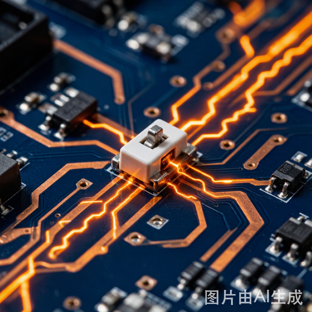
Copper trace fusing is a critical failure mode in SMT power electronics that occurs when excessive current generates enough I²R heat to melt the copper conductor. While modern PCB design prioritizes controlled impedance and signal integrity, the fundamental physics of conductor fusing remains essential for safety-critical designs.
Short-circuit conditions can deliver currents 10–100 times the normal operating level. Without proper trace sizing and protection coordination, copper traces can vaporize in milliseconds, causing catastrophic board damage, fire hazards, and system-wide failures.
The Physics of Copper Trace Fusing
When current flows through a copper trace, resistive heating raises the conductor temperature according to Joule’s law: P = I²R. Under steady-state conditions, heat dissipation through convection, conduction, and radiation balances the generated heat. But during a short circuit, the current surges so rapidly that there is insufficient time for heat dissipation—adiabatic heating dominates.
The copper trace undergoes three phases during a fusing event:
- Heating phase: Temperature rises from ambient toward the melting point of copper (1085°C). The resistivity increases with temperature (temperature coefficient α ≈ 0.0039/°C), accelerating I²R heating in a positive feedback loop.
- Melting phase: At 1085°C, the copper absorbs latent heat of fusion (206 kJ/kg) while transitioning from solid to liquid. The trace cross-section begins to deform.
- Vaporization: If current continues flowing, the liquid copper reaches its boiling point (2562°C) and vaporizes, creating an arc plasma that can ignite the PCB substrate.
The Onderdonk Equation for Fusing Current
The industry-standard Onderdonk equation predicts the fusing current for a given conductor cross-section and time duration:
I_fuse = A × √(log((T_melt − T_ambient) / (234 + T_ambient) + 1) / t)
Where I_fuse is the fusing current in amperes, A is the cross-sectional area in circular mils, T_melt is the melting point of copper (1083°C), T_ambient is the ambient temperature, and t is the time in seconds.
For a 1 oz copper trace (35 μm thick, 1 mm wide, giving approximately 1970 circular mils cross-section), the fusing current at 25°C ambient is approximately:
- 1 second: ~250 A
- 100 ms: ~790 A
- 10 ms: ~2,500 A
- 1 ms: ~7,900 A
IPC-2152: Standard for Trace Current Capacity
While the Onderdonk equation models fusing conditions, IPC-2152 provides the standard methodology for determining trace current capacity under normal operating conditions. The standard includes charts and derating factors for:
- Internal vs. external layers: External traces dissipate heat more effectively than internal traces (approximately 2× current capacity for the same temperature rise).
- Copper weight: 0.5 oz, 1 oz, 2 oz, 3 oz, and heavy copper options (up to 10 oz for power electronics).
- Temperature rise limits: Typically 10°C, 20°C, or 40°C above ambient, depending on reliability requirements.
- Plane proximity: Traces near copper planes benefit from enhanced heat spreading.
Short-Circuit Protection Design Strategy
Effective protection requires a coordinated approach matching fuse or circuit breaker characteristics to the trace fusing curve:
- Calculate the trace I²t withstand: Using the Onderdonk equation, determine the energy (I²t) required to fuse each critical trace segment.
- Select protection device with lower I²t: The protection device (fuse, PTC resettable fuse, or electronic fuse IC) must have a clearing I²t value below the trace’s fusing I²t across the entire fault current range.
- Account for derating: Apply temperature derating (typically 25% at 85°C ambient) and altitude derating for convection-cooled designs.
- Verify coordination: Ensure that upstream protection operates before downstream traces fuse, preventing cascading failures.
Practical Design Guidelines
For SMT power electronics operating in Southeast Asian tropical environments with ambient temperatures reaching 40–45°C inside enclosures, designers should apply a 1.5× safety factor to all current capacity calculations. Heavy copper PCBs (3–10 oz) provide margin for power distribution traces, but careful attention must be paid to the transition zones where trace width changes—these are the most common fusing failure points due to current crowding.
Thermal imaging and DC IR drop testing during prototype validation can identify hot spots before they become field failures. For mission-critical designs, incorporating dedicated current-sensing and fast-acting electronic fuse ICs provides microsecond-level protection that passive fuses ca
ot match.



