Introduction
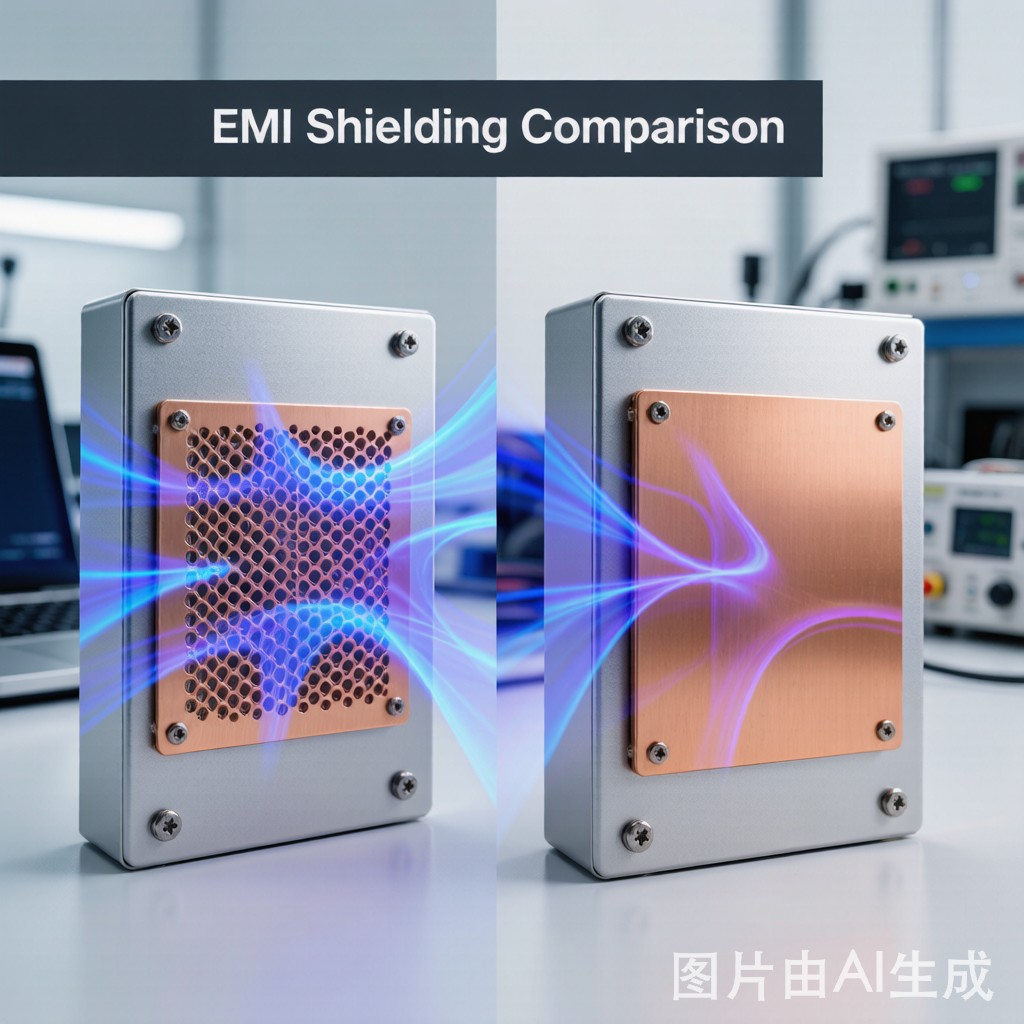
EMI shielding design for power electronics enclosures presents a challenging trade-off: solid copper sheets provide maximum shielding effectiveness, but they block airflow essential for cooling high-power components. Copper mesh offers ventilation at the cost of reduced shielding performance, especially at higher frequencies. For design engineers and procurement specialists sourcing shielding materials in Southeast Asia, understanding where each solution excels — and where it fails — is essential for making informed design decisions.
Shielding Effectiveness Fundamentals
How Shielding Works
Electromagnetic shielding operates through three mechanisms: reflection loss (R), absorption loss (A), and multiple-reflection correction (B). For copper, reflection loss dominates at low frequencies due to the impedance mismatch between the incoming wave (377 Ω in free space) and the shield surface (milliohms for copper). Absorption loss increases with frequency and material thickness due to the skin effect, where current flows only within a thin surface layer.
Skin Depth Calculation for Copper
At 1 MHz, the skin depth in copper is approximately 66 μm. At 100 MHz, it drops to 6.6 μm. At 1 GHz, only 2.1 μm. This means that even very thin copper layers provide excellent absorption at high frequencies — but only if the shield is continuous. Apertures in the shield (such as mesh holes) create leakage paths that determine real-world performance.
Opening Size and Shielding Effectiveness: The SE Degradation Formula
For a single aperture, shielding effectiveness degrades according to SE(dB) = 20 log₁₀(λ/2L), where λ is the wavelength and L is the longest dimension of the aperture. A 2 mm mesh opening provides approximately 37 dB of attenuation at 1 GHz, compared to >100 dB for a solid copper sheet at the same frequency. However, at 100 MHz, the same mesh opening degrades to only 17 dB — the larger wavelength makes the aperture electrically larger.
| Frequency | Solid Copper (0.2mm) | Copper Mesh (2mm opening) | Copper Mesh (5mm opening) |
|---|---|---|---|
| 30 MHz | >100 dB | ~14 dB | ~6 dB |
| 100 MHz | >100 dB | ~17 dB | ~9 dB |
| 500 MHz | >100 dB | ~30 dB | ~20 dB |
| 1 GHz | >100 dB | ~37 dB | ~26 dB |
| 3 GHz | >100 dB | ~45 dB | ~35 dB |
Ventilation and Thermal Management Trade-Off
Airflow Through Copper Mesh
A 2mm-opening copper mesh with 0.3mm wire diameter provides approximately 75% open area, allowing substantial natural convection airflow. For a typical 100W power electronics enclosure, this translates to a 10-15°C reduction in internal ambient temperature compared to a sealed solid shield design. For forced-air cooling, the pressure drop across a 2mm mesh at 1 m/s face velocity is typically 5-10 Pa — negligible for most fan systems.
When Solid Shields Are Non-Negotiable
Solid copper shields become mandatory when: (1) the emission frequency is below 50 MHz, where mesh provides less than 20 dB attenuation; (2) regulatory compliance (FCC Part 15 Class B, CISPR 32) requires >40 dB margin; (3) the enclosure contains high-sensitivity receivers vulnerable to external interference. In these cases, thermal management must be addressed through alternative means: dedicated heatsinks, heat pipes, or thermoelectric cooling rather than enclosure-level ventilation.
Hybrid Solutions: The Best of Both Worlds
For many power electronics applications, a hybrid approach combining solid copper sheet in high-emission areas with copper mesh ventilation panels in low-emission zones offers the optimal balance. A typical implementation uses solid copper over the power switching section (where conducted and radiated EMI is highest) and copper mesh over passive component areas (where ventilation is needed and EMI levels are lower). This approach can achieve 60-80 dB overall shielding effectiveness while maintaining adequate cooling airflow.
Installation and Grounding Best Practices
Both mesh and solid shields require low-impedance grounding to the enclosure chassis. For copper mesh, a continuous conductive gasket (beryllium copper fingerstock or conductive elastomer) along the entire perimeter is essential — point-contact grounding creates slot ante
as that radiate EMI. For solid copper sheet, edge plating or a formed lip with spring-finger contact ensures consistent perimeter grounding. In both cases, the gap between grounding points should not exceed λ/20 at the highest frequency of concern.
Selection Guide
| Application | Recommended Solution | Key Consideration |
|---|---|---|
| Server power supply (>500W) | Solid copper + forced air ducting | Regulatory compliance requires >40 dB margin |
| LED driver (50-150W) | Copper mesh (2mm opening) | Adequate SE above 100 MHz, passive cooling |
| Industrial motor drive | Hybrid solid + mesh | High low-frequency EMI from switching |
| Telecom base station | Solid copper (sealed enclosure) | Receiver sensitivity requirements |
Conclusion
Copper mesh and solid copper sheet serve different masters in EMI shielding design. Mesh prioritizes thermal management; solid sheet prioritizes shielding performance. The decision is not binary — it is a frequency-dependent, application-specific optimization that balances regulatory compliance, thermal requirements, and cost. For most power electronics in the 100W-1kW range operating above 100 MHz, 2mm-opening copper mesh provides an excellent compromise, delivering 30-45 dB shielding while allowing natural convection cooling that extends component lifetime.



