Introduction
Electromagnetic interference shielding in consumer electronics has two dominant approaches: conductive coating applied by spray or brushing, and stamped metal shielding cans soldered to the PCB. Each method has distinct advantages and limitations that affect shielding effectiveness, manufacturing cost, rework flexibility, and thermal performance. Choosing between them requires understanding not just the dB of attenuation each provides, but how they integrate into the complete product design and production workflow.
Conductive Coating Overview
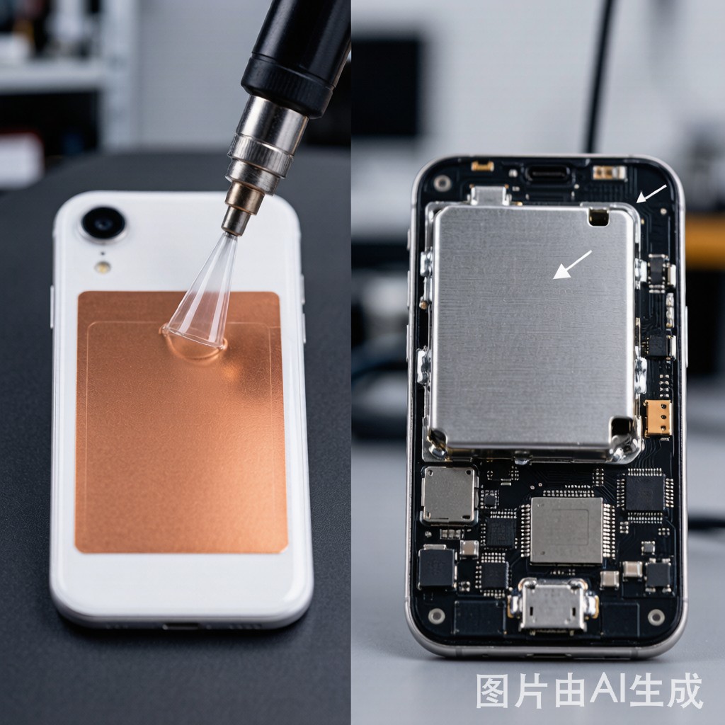
Conductive coatings are paint-like materials loaded with metallic particles—typically silver, copper, nickel, or graphite—that provide a conductive surface when applied to a plastic housing or internal partition. They are applied by spray gun, brush, or dip coating inside the product enclosure or on separate plastic shield inserts. After drying or curing, the coating forms a continuous conductive layer that reflects and absorbs electromagnetic energy.
The most common conductive coating types include silver-based paints for the highest conductivity and shielding effectiveness, nickel-based coatings for moderate performance at lower cost, and copper-filled sprays that offer good conductivity but may require an overcoat to prevent oxidation. Carbon-based coatings provide the lowest shielding effectiveness but are the cheapest option for applications where only modest attenuation is needed.
Metal Shielding Can Overview
Stamped metal shielding cans are rigid enclosures made from thin sheet metal—typically 0.2 to 0.5 mm copper, brass, nickel-silver, or stainless steel—that are placed over noisy components and soldered to ground pads on the PCB. They create a defined Faraday cage around the shielded area with predictable shielding effectiveness across a wide frequency range. The cans can be one-piece solid covers or two-piece designs with a removable lid for rework access.
Copper and nickel-silver cans are the most common choice for consumer electronics because they combine good conductivity with ease of stamping and soldering. Brass cans are used when slightly higher stiffness is needed, and stainless steel is reserved for harsh environments where corrosion resistance matters more than solderability. The can height typically ranges from 2 to 8 mm depending on the tallest component under the shield.
Shielding Effectiveness Comparison
| Frequency Range | Conductive Coating | Metal Shielding Can |
|---|---|---|
| 10 MHz – 100 MHz | 20 – 40 dB | 50 – 70 dB |
| 100 MHz – 1 GHz | 30 – 50 dB | 60 – 80 dB |
| 1 GHz – 5 GHz | 25 – 45 dB | 50 – 70 dB |
| 5 GHz – 10 GHz | 20 – 35 dB | 40 – 60 dB |
Cost and Manufacturing Considerations
Conductive coating has a lower material cost per unit but higher process complexity. The coating must be applied in a controlled environment with proper ventilation, masking of non-coated areas, and curing time. Spray equipment maintenance, coating thickness uniformity, and quality inspection add labor and overhead. For high-volume production, automated spray systems reduce the per-unit cost, but the initial setup investment is significant.
Metal shielding cans have a higher per-unit material cost but integrate directly into the standard SMT assembly process. The can is placed by the pick-and-place machine or manually and soldered during reflow alongside other components. No separate coating step, curing time, or masking is required. For designs with multiple shielded areas, a single stamped can can cover several modules at once, reducing the total number of shield components compared to individual coatings.
Rework and Repair Flexibility
Rework is where the two methods diverge most significantly. Conductive coating inside a plastic housing is essentially permanent for the life of that housing. If a component under the coated area needs replacement, the technician must remove the housing, access the PCB, and hope the coating does not flake or lose conductivity during handling. Re-coating after repair is rarely practical in a service center.
Two-piece metal shielding cans with removable lids solve this problem elegantly. The lid clips or slides off, exposing the components for inspection and repair, and then re-clips without any soldering or reflow. One-piece cans require desoldering, which adds thermal cycles to the board and risks damaging nearby components. The rework decision therefore favors two-piece cans for any product that expects field service.
Thermal Management Implications
Conductive coating has a negligible effect on thermal management because the thin coating layer does not conduct significant heat away from the shielded components. The plastic housing underneath acts as a thermal insulator, and any heat generated inside the shielded zone must escape through PCB conduction or ventilation openings.
Metal shielding cans, by contrast, can serve as heat spreaders. A copper can soldered to the PCB ground plane conducts heat from hot components through the can walls to the PCB copper and then to the product chassis. Some designers intentionally use taller cans with ventilation slots to combine EMI shielding with convective cooling. The trade-off is that slots reduce shielding effectiveness at the slot frequency, so the slot dimensions must be carefully calculated based on the highest frequency that needs attenuation.
Design Selection Guide
Choosing between conductive coating and metal shielding cans depends on the product requirements across five dimensions: shielding level, cost structure, rework needs, thermal budget, and form factor constraints. For compact consumer devices like smartwatches where internal volume is extremely limited, conductive coating on the housing i
er surface may be the only feasible approach. For smartphones and tablets with multiple RF modules and moderate rework expectations, two-piece metal cans are the standard choice.
In many products, a hybrid approach works best. Metal cans shield the most sensitive RF modules and the noisiest digital blocks, while conductive coating handles areas where cans ca
ot fit or where the shielding requirement is modest. This combination maximizes overall EMI performance while keeping cost and manufacturing complexity within acceptable limits.
Conclusion
Neither conductive coating nor metal shielding cans is universally superior. Conductive coating offers flexibility in shape and application, lower material cost, and compatibility with ultra-thin housings. Metal cans provide higher shielding effectiveness, easier rework access with two-piece designs, and thermal spreading capability. The optimal choice depends on the specific product’s EMI targets, cost model, service strategy, and thermal constraints. In practice, the best results often come from combining both methods strategically across the PCB layout.



