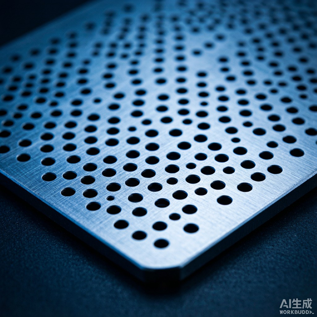
As 5G millimeter-wave (mmWave) frequencies push into the 24–40 GHz range, conventional solid metal EMI shield cans introduce a new challenge: cavity resonance. The shielded enclosure itself becomes a resonant cavity, amplifying specific frequencies and causing signal integrity degradation, ante
a detuning, and even oscillation in nearby active circuits. Perforated mesh shielding offers a engineered solution—sub-wavelength aperture arrays that maintain shielding effectiveness while disrupting standing-wave formation. This article provides the design methodology, performance data, and practical selection criteria for perforated mesh EMI shields in 5G mmWave applications.
Understanding Cavity Resonance in Shielded Enclosures
Resonant Frequency Calculation
A rectangular shielded cavity with dimensions a × b × d supports transverse electric (TE) and transverse magnetic (TM) modes at frequencies determined by:
f(m,n,p) = (c/2) × √[(m/a)² + (n/b)² + (p/d)²]
where m, n, p are mode indices (0, 1, 2, …) and c is the speed of light. For a typical 5G module shield can measuring 20 × 15 × 3 mm, the fundamental TE₁₀₁ mode resonates at approximately:
f₁₀₁ = (3×10⁸/2) × √[(1/0.020)² + (0/0.015)² + (1/0.003)²] ≈ 51.5 GHz
However, higher-order modes populate densely above 24 GHz. A 25 × 20 × 5 mm enclosure has 12 resonant modes between 24 and 40 GHz, each capable of trapping and amplifying mmWave energy by 10–25 dB at the cavity walls.
Impact on 5G Module Performance
- Ante
a desense:
Cavity resonance creates reflected fields that detune phased array anteas, reducing effective isotropic radiated power (EIRP) by 3–8 dB
- Receiver sensitivity degradation: Resonant amplification of self-interference raises the noise floor by 5–15 dB in affected bands
- Power amplifier instability: Reflected energy at resonance frequencies can cause PA oscillation and efficiency collapse
Perforated Mesh Design Principles
Waveguide-Below-Cutoff (WBC) Aperture Theory
Each aperture in the mesh acts as a waveguide-below-cutoff. For a circular aperture of diameter D in a metal sheet of thickness t, the cutoff frequency is:
f_c = c / (1.706 × D)
At frequencies well below f_c, the shielding effectiveness of a single aperture is:
SE_aperture = 20 × log₁₀(λ / 2D) + 32 (for t ≈ 0)
For 28 GHz operation (λ = 10.7 mm), a 1.0 mm diameter aperture provides approximately 46 dB of shielding per aperture. However, the total SE of a perforated panel depends on the number and spacing of apertures.
Multi-Aperture Shielding Effectiveness
For an N × M array of identical apertures with center-to-center spacing S, the total SE degrades from the single-aperture value according to the coupling between adjacent openings. The empirical formula for a regularly spaced array:
SE_total = SE_single − 20 × log₁₀(N_total) + coupling_correction
where coupling_correction accounts for mutual impedance between apertures, typically 3–8 dB for spacing ratios S/D > 2.
Aperture Pattern Comparison
| Pattern | Hole Size (mm) | Pitch (mm) | Open Area (%) | SE at 28 GHz (dB) | Airflow (m³/h·m²) |
|---|---|---|---|---|---|
| Circular (dense) | 0.5 | 1.0 | 20 | 55 | 1,200 |
| Circular (standard) | 1.0 | 2.0 | 20 | 46 | 2,400 |
| Circular (ventilated) | 1.5 | 3.0 | 20 | 38 | 3,600 |
| Hexagonal (dense) | 0.5 | 1.0 | 23 | 53 | 1,380 |
| Hexagonal (standard) | 1.0 | 2.0 | 23 | 44 | 2,760 |
| Square slot | 0.5 × 0.5 | 1.0 | 25 | 48 | 3,000 |
Hexagonal patterns offer the best open-area-to-SE ratio due to their efficient tessellation geometry, while circular apertures provide superior multi-frequency performance because they avoid polarization-dependent coupling that affects slot-shaped openings.
Cavity Resonance Suppression Mechanism
Mode Disruption Through Aperture Coupling
Unlike solid shield cans that reflect all incident energy back into the cavity, perforated mesh allows a controlled fraction of the resonant field to leak through the apertures. This leakage attenuates the quality factor (Q) of each resonant mode:
Q_perforated = Q_solid / (1 + η × N_apertures)
where η is the coupling coefficient per aperture (typically 0.01–0.05 for sub-wavelength holes). For a 20 × 15 mm shield lid with 300 apertures of 0.5 mm diameter:
- Q_solid ≈ 500–800 (depending on surface conductivity)
- Q_perforated ≈ 50–80 (with η ≈ 0.03)
The 10× reduction in Q transforms sharp resonance peaks (±20 dB) into broad, manageable humps (±3–5 dB), restoring usable bandwidth across the entire 5G n257/n258/n261 bands.
Resonance Frequency Shift
The effective cavity dimensions also increase slightly due to aperture fringing fields, shifting resonance frequencies by 2–5% higher. This shift can move a problematic resonance out of the operating band entirely in some module designs.
Material and Manufacturing Considerations
Material Selection
| Material | Thickness (mm) | SE at 28 GHz (dB) | Corrosion Resistance | Cost Factor |
|---|---|---|---|---|
| SUS 304 stainless | 0.2 | 50–55 | Excellent | 1.0× |
| C7521 nickel silver | 0.2 | 48–52 | Very good | 1.2× |
| C2680 brass (Ni plated) | 0.2 | 46–50 | Good | 0.8× |
| Aluminum 5052 | 0.3 | 42–46 | Fair (anodize req.) | 0.6× |
Photochemical Etching vs Laser Drilling
For aperture diameters below 0.5 mm, two manufacturing methods dominate:
- Photochemical etching (PCM): Produces burr-free apertures with ±0.02 mm tolerance, suitable for high-volume production (10,000+ pieces/month). Minimum hole diameter equals material thickness (D_min ≈ t).
- Femtosecond laser drilling: Achieves D/t ratios as low as 0.3, enabling 0.15 mm holes in 0.5 mm thick material. Higher cost per piece but offers design flexibility for prototypes and low-volume production.
Thermal-Ventilation Integration
In 5G mmWave modules generating 5–15 W of heat in compact footprints, the shield lid often serves double duty as a ventilation path. A perforated mesh with 20% open area and 1.0 mm circular apertures provides 2,400 m³/h·m² airflow—sufficient to support forced convection cooling with a 40 mm blower delivering 3–5 CFM. The pressure drop across the mesh is minimal (ΔP < 2 Pa at typical module flow rates), ensuring that the acoustic noise from the cooling fan remains acceptable.
Conclusion
Perforated mesh EMI shielding addresses the dual challenges of cavity resonance suppression and thermal ventilation in 5G mmWave module enclosures. By selecting sub-wavelength aperture dimensions (D < λ/10) and optimizing pattern geometry, designers can achieve 40–55 dB shielding effectiveness at 28 GHz while reducing cavity Q by an order of magnitude. The hexagonal aperture pattern at 0.5 mm diameter with 1.0 mm pitch represents the recommended starting point for new 5G mmWave module designs, offering the best balance of shielding performance, airflow, and manufacturability for Southeast Asian electronics manufacturing.



