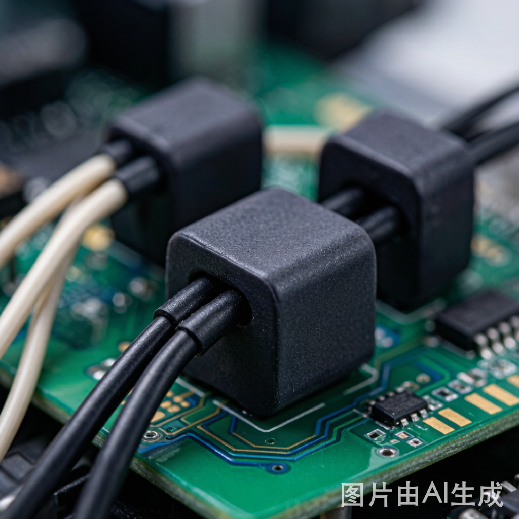
Introduction: The Conducted EMI Problem in SMT Production Environments
Surface-mount technology (SMT) production lines concentrate dozens of high-power, high-frequency devices — reflow ovens drawing 25–50 kW with PWM-controlled heaters, pick-and-place machines with 20+ servo axes switching at kHz frequencies, and automated optical inspection systems with high-intensity LED strobe illumination — all operating within a single factory floor. The resulting conducted electromagnetic interference (EMI) on power cables, if not properly suppressed, degrades the performance of sensitive measurement equipment (AOI cameras, SPI laser sensors), causes intermittent communication failures in MES/SCADA networks, and may exceed regulatory limits for conducted emissions (CISPR 11/32 Class A industrial limits: 79 dBμV quasi-peak from 150 kHz to 30 MHz).
Ferrite EMI suppression cores clamped onto power cables provide a cost-effective, retrofittable, and maintenance-free solution for conducted emission reduction. This article compares the two dominant form factors — split core and solid core — with detailed impedance performance data and practical installation guidance for SMT production environments.
Ferrite Core Physics: How Suppression Works
Impedance Transformation Mechanism
A ferrite core placed around a conductor creates a frequency-dependent series impedance that attenuates high-frequency noise currents while remaining transparent (low impedance) at the 50/60 Hz power frequency. The core operates as a common-mode choke: noise currents flowing on both the line and neutral conductors in the same direction (common-mode) encounter the full ferrite impedance, while the 50/60 Hz load current flowing in opposite directions on line and neutral (differential-mode) produces canceling magnetic fields and encounters near-zero impedance.
The suppression performance is quantified as insertion loss:
IL(dB) = 20 × log₁₀((Z_source + Z_load + Z_ferrite) / (Z_source + Z_load))
Where Z_ferrite is the complex impedance of the ferrite core at the noise frequency. For optimal suppression, Z_ferrite should be large relative to the source and load impedances of the noise path (typically 50–150 Ω for conducted EMI paths per CISPR 16-2-1 LISN specifications).
Ferrite Material Families: MnZn vs NiZn
| Material | μᵢ (initial permeability) | Optimal Frequency Range | Curie Temp | Cost | Best Application |
|---|---|---|---|---|---|
| MnZn (manganese-zinc) | 1,000–15,000 | 10 kHz – 10 MHz | 120–220°C | Low | Conducted EMI (150 kHz–30 MHz) |
| NiZn (nickel-zinc) | 10–2,500 | 1 MHz – 1 GHz | 200–350°C | Medium | Radiated EMI, high-frequency suppression |
| Nano-crystalline | 20,000–100,000 | 1 kHz – 100 kHz | 570°C | High | Low-frequency high-current CM chokes |
For SMT equipment conducted EMI (150 kHz – 30 MHz regulatory band), MnZn ferrite with μᵢ = 2,000–5,000 offers the optimal impedance profile. NiZn is preferred for suppressing noise above 30 MHz (radiated EMI in automation communication cables).
Solid Core Ferrite Suppression Cores
Design and Impedance Characteristics
Solid core ferrite suppressors are toroidal or cylindrical cores that must be installed during cable assembly — the cable is threaded through the core before co
ector termination. Once installed, they provide the highest possible impedance per unit volume because the magnetic circuit is continuous (no air gap).
| Parameter | Typical Range | Notes |
|---|---|---|
| Core OD/ID/Length | 15–40 mm / 5–15 mm / 20–60 mm | OD determines max impedance |
| μᵢ (MnZn, standard grade) | 2,000–5,000 | Higher μ = higher low-freq impedance |
| Z @ 1 MHz (single turn) | 50–250 Ω | Proportional to core cross-section |
| Z @ 10 MHz (single turn) | 100–500 Ω | Higher μ grades peak earlier |
| Z @ 100 kHz (single turn) | 10–50 Ω | Lower μ grades better at HF |
| Multi-turn Z multiplier | N² (theoretical) | Practical: ~N¹·⁸ due to parasitic capacitance |
| Max operating temperature | 105–125°C (MnZn) | Derating above 80°C for some grades |
| Saturation current (single turn) | 3–10 A (ferrite cross-section dependent) | Must exceed peak load current |
Advantages:
– Maximum impedance per unit volume (no air gap in magnetic circuit)
– Lower cost per unit (simpler manufacturing — no mechanical clamp/hinge assembly)
– Reliable long-term performance (no mechanical interfaces to degrade or become misaligned)
– Multi-turn winding possible for N² impedance multiplication
Limitations:
– Must be installed during cable assembly (pre-termination)
– Ca
ot be retrofitted to existing installed cables
– Cable replacement requires new core
– Single-turn only for co
ectors larger than core ID
Split Core Ferrite Suppression Cores
Design and Mechanical Construction
Split core ferrite suppressors consist of two ferrite half-cylinders held together by a plastic snap-fit housing (typically nylon PA66-GF15), with a spring-loaded hinge mechanism ensuring precise mating of the ferrite halves. The cable is placed into one half, and the second half is snapped closed around it — installation takes seconds without disco
ecting the cable.
| Parameter | Typical Range | Notes |
|---|---|---|
| Core ID range | 3–35 mm | Must match cable OD + 1–2 mm clearance |
| Housing material | PA66-GF15, UL94 V-0 | Must withstand cable operating temperature |
| Air gap (closed) | 5–20 μm | Surface finish and spring force determine gap |
| μₑ (effective permeability) | 300–800 | Reduced by air gap — see formula below |
| Z @ 1 MHz (single turn), same core volume as solid | 30–80 Ω | ≈50–65% of solid core impedance |
| Z @ 10 MHz (single turn) | 80–250 Ω | Reduced proportionally to μₑ |
| Closing force | 5–15 N (spring mechanism) | Must maintain closure under vibration |
| Retention (vibration) | 5–10 G, 10–2000 Hz | Per IEC 60068-2-6 for industrial environments |
Air Gap Effect on Impedance
The unavoidable air gap in split cores dramatically affects effective permeability:
μₑ = μᵢ / (1 + (μᵢ × g / lₑ))
Where:
– μᵢ = initial permeability of ferrite material (e.g., 2,500)
– g = total air gap length (10–20 μm for well-machined split cores)
– lₑ = effective magnetic path length (typically 50–80 mm for common core sizes)
For μᵢ = 2,500, g = 15 μm, lₑ = 60 mm: μₑ = 2,500 / (1 + (2,500 × 0.015 / 60)) = 2,500 / 1.625 ≈ 1,540 — a 38% reduction from the material’s intrinsic permeability. This translates directly to a proportional reduction in low-frequency impedance.
However, at frequencies above 3–5 MHz, the material’s intrinsic permeability begins to roll off (Snoek’s limit for MnZn ferrites), and the air gap penalty diminishes — meaning split cores perform closer to solid cores in the higher frequency portion of the conducted EMI band (10–30 MHz).
Advantages:
– Retrofittable — installs in seconds without cable disco
ection
– Reusable — transfer to new cable when cable is replaced
– Serviceable — inspect, clean, replace without cable work
– Multiple core stacking along cable for cumulative impedance
Limitations:
– 35–50% impedance reduction vs equivalent solid core due to air gap
– Higher unit cost (plastic housing, spring mechanism, assembly labor)
– Mechanical closure must be verified (open-core = no suppression)
– Slightly larger OD footprint (housing adds 3–5 mm radial)
Comparative Impedance Performance
| Frequency | Solid Core Z (Ω) (MnZn μᵢ=2500, 28×13×29mm) |
Split Core Z (Ω) (same ferrite volume) |
Split/Solid Ratio |
|---|---|---|---|
| 100 kHz | 35 | 20 | 57% |
| 1 MHz | 120 | 70 | 58% |
| 5 MHz | 180 | 125 | 69% |
| 10 MHz | 320 | 230 | 72% |
| 30 MHz | 280 | 220 | 79% |
| 100 MHz | 180 | 155 | 86% |
The split/solid impedance ratio improves with frequency as the material permeability drops and the air gap becomes a smaller fraction of the total magnetic reluctance. For conducted EMI suppression in the critical 150 kHz – 30 MHz band, split cores provide 55–80% of solid core performance — adequate for many applications where a 6–10 dB insertion loss is sufficient.
Installation Best Practices for SMT Production Equipment
Cable Selection and Core Placement
Placement position: Ferrite cores should be placed as close to the noise source (equipment end) as practical — within 50–100 mm of the cable entry point to the equipment enclosure. This maximizes the impedance seen by noise currents before they radiate from the cable acting as an ante
a.
Cable diameter matching: The core ID must snugly fit the cable OD. A gap between the cable jacket and the core ID allows magnetic flux leakage, reducing effective permeability. For cables with OD of 7.0 mm, select core ID of 7.0–8.0 mm (not 10 mm or larger).
Multi-turn winding (solid core only): Passing the cable through the core 2–3 times (if cable length permits) increases impedance by approximately N¹·⁸:
– 1 turn: Z (baseline)
– 2 turns: 2¹·⁸ × Z ≈ 3.5Z (+11 dB)
– 3 turns: 3¹·⁸ × Z ≈ 7.2Z (+17 dB)
However, multi-turn winding increases parasitic turn-to-turn capacitance, shifting the impedance peak to lower frequencies. For conducted EMI above 10 MHz, single-turn is often more effective.
Multiple core stacking: For split cores, placing multiple cores along the cable (spaced 20–30 mm apart to avoid magnetic coupling between adjacent cores) adds impedance cumulatively. 2–3 split cores can match or exceed a single solid core’s impedance in the 1–30 MHz range.
Industrial Environment Considerations
Vibration resistance: SMT pick-and-place machines generate continuous vibration (2–5 G, 20–500 Hz). Split core snap-fit housings must be verified for closure retention under these conditions. Clip-on cable ties securing the core housing to the cable provide secondary retention.
Temperature derating: MnZn ferrite impedance decreases with temperature — typically —0.5 to —1.0% per °C above 25°C. Near reflow ovens (ambient 45–55°C), the impedance may drop 10–30%. Specify ferrite grades with higher Curie temperature (≥180°C) for hot-zone installations.
Oil and chemical resistance: SMT production environments expose cables and cores to flux residue, cleaning solvents, and machine oils. Split core housing material (typically PA66-GF15) is resistant to common industrial chemicals, but prolonged exposure to strong solvents (acetone, MEK) can embrittle the snap-fit mechanism.
Selection Decision Matrix for SMT Production Environments
| Application Scenario | Recommended Core Type | Rationale |
|---|---|---|
| New equipment installation | Solid core | Pre-termination installation possible; maximum impedance |
| Retrofit existing power cables | Split core | Only option without cable re-termination |
| Critical measurement equipment (AOI/SPI) | Solid core, 2–3 turns | Maximum suppression required for sensitive instruments |
| Reflow oven power cables (25–50A, hot zone) | Split core, high-temp MnZn grade | Retrofit compatibility, high-temp ferrite grade (Tc >200°C) |
| Motor drive cables (PWM, 5–20 kHz fundamental) | Nano-crystalline solid core | High μ for low-frequency EMI, high saturation current |
| Automation comm cables (Ethernet, RS-485) | NiZn split core | High-frequency suppression, retrofit, multi-core stacking |
Conclusion
Ferrite EMI suppression cores are the most cost-effective first-line defense against conducted emissions in SMT production environments. Solid cores deliver maximum impedance (100% baseline) but require pre-termination installation. Split cores provide 55–80% of solid core impedance with the decisive advantage of retrofit installation in seconds — a critical differentiator for existing production lines where cable re-termination is impractical or cost-prohibitive. For new installations, specify solid cores. For retrofit, stack 2–3 split cores to achieve equivalent suppression. MnZn ferrite (μᵢ 2,000–5,000) is the optimal material for the 150 kHz – 30 MHz conducted emission band; NiZn is preferred for communication cable radiated EMI above 30 MHz. Regular verification of split core closure integrity, especially in high-vibration SMT environments, ensures continued suppression effectiveness over the equipment lifecycle.



