Introduction: Engineering Guard Booths for Extreme Wind Events
Guard booths and security kiosks deployed at industrial facilities, ports, commercial complexes, and transportation hubs across Southeast Asia must withstand some of the world’s most severe wind conditions. The region experiences an average of 20–30 tropical cyclones a
ually, with typhoon categories reaching sustained wind speeds of 200–250 km/h (Super Typhoon equivalent to Category 4–5 on the Saffir-Simpson scale). A guard booth that collapses during a typhoon not only represents a property loss but creates dangerous flying debris and endangers any occupants who may be sheltering inside. Proper wind load structural design is therefore a life-safety engineering requirement, not merely a code compliance exercise.
Southeast Asian Wind Climate and Design Wind Speeds
Regional Wind Speed Mapping
Wind load design begins with establishing the basic wind speed (V) for the installation location. ASCE 7-22 provides wind speed maps for various risk categories, and regional building codes supplement these with local data. For Southeast Asian locations, the design basic wind speeds (3-second gust at 10m height, Exposure C, open terrain) are approximately:
| Location | Basic Wind Speed (km/h) | Return Period | Risk Category |
|---|---|---|---|
| Philippines (eastern coast) | 285–315 | 50-year | II (essential) |
| Philippines (Manila, western) | 250–265 | 50-year | II |
| Vietnam (central coast) | 250–280 | 50-year | II |
| Vietnam (Hanoi, inland) | 200–230 | 50-year | II |
| Thailand (coastal) | 195–215 | 50-year | II |
| Thailand (Bangkok, inland) | 160–180 | 50-year | II |
| Malaysia (east coast, monsoon) | 165–185 | 50-year | II |
| Indonesia (general) | 150–170 | 50-year | II |
For guard booths classified as Risk Category IV (essential facilities—security checkpoints at critical infrastructure), the design wind speed should be based on a 100-year or 1700-year return period per ASCE 7-22, increasing V by approximately 10–15% over the 50-year values shown above.
Exposure Category Selection
ASCE 7-22 defines exposure categories based on surface roughness. Guard booths are typically installed in open areas (parking lots, facility perimeters, roadside locations) and should be designed for Exposure C (open terrain with scattered obstructions). For booths in dense urban settings surrounded by buildings of similar height, Exposure B may apply, reducing wind pressures by 20–35%. However, it is conservative practice to design for Exposure C unless the urban context is guaranteed for the booth’s entire service life.
Wind Load Calculation Methodology per ASCE 7-22
Velocity Pressure
The velocity pressure (qz) at height z is calculated as:
qz = 0.613 × Kz × Kzt × Kd × Ke × V² (Pa, where V is in m/s)
Where:
- Kz = velocity pressure exposure coefficient (0.85 for Exposure C at z = 4.6m / 15 ft)
- Kzt = topographic factor (1.0 for flat terrain; up to 2.0 for hilltops/escarpments)
- Kd = wind directionality factor (0.85 for buildings)
- Ke = ground elevation factor (1.0 at sea level; 0.92 at 1500m)
- V = basic wind speed (m/s)
For a guard booth in Manila (V = 260 km/h = 72.2 m/s) at 3m height, Exposure C:
qz = 0.613 × 0.85 × 1.0 × 0.85 × 1.0 × (72.2)² = 2,300 Pa (2.3 kPa)
MWFRS vs Components and Cladding (C&C)
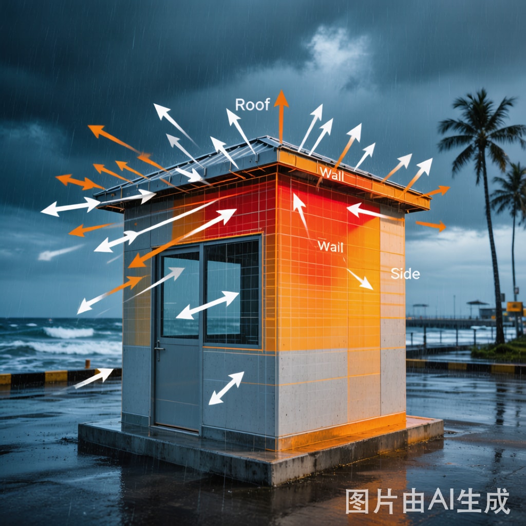
ASCE 7-22 distinguishes between Main Wind-Force Resisting System (MWFRS) loads—applied to the overall structural frame—and Component and Cladding (C&C) loads—applied to individual elements such as wall panels, glazing, and roofing. C&C loads are typically higher because they account for localized pressure peaks at edges and corners.
For a typical guard booth (3m × 3m × 3m height), the design wind pressures are:
| Surface | MWFRS Pressure (kPa) | C&C Pressure (kPa) | Direction |
|---|---|---|---|
| Windward wall | +1.38 | +1.73 | Pressure (inward) |
| Leeward wall | -0.69 | -1.15 | Suction (outward) |
| Side walls (center) | -0.46 | -1.15 | Suction (outward) |
| Side walls (edge zones) | -0.69 | -2.30 | Suction (outward) |
| Roof (center) | -0.92 | -2.53 | Uplift |
| Roof (edge/corner) | -1.84 | -4.60 | Uplift (critical) |
The roof corner zone experiences the highest localized uplift forces (-4.60 kPa in C&C), making roof-to-wall co
ections and roofing panel fasteners the most critical design elements for typhoon resistance.
Structural Frame Design
Steel Frame Selection
For a guard booth designed to withstand typhoon-level winds, the primary structural frame should be fabricated from structural steel with the following minimum specifications:
- Columns: Square Hollow Section (SHS) 100×100×4 mm, Q355 steel (fy = 355 MPa). Four corner columns provide the MWFRS.
- Wall girts: SHS 60×40×3 mm at 600 mm vertical spacing, supporting wall panels against C&C wind pressure
- Roof beams: SHS 80×80×4 mm spa
ing between columns, designed for combined gravity + uplift loading
- Roof purlins: Cold-formed C-section 100×50×20×2 mm at 600 mm spacing
- Base frame: SHS 100×100×6 mm welded frame with anchor plate for foundation bolting
All steel components must be hot-dip galvanized (minimum 75 μm zinc coating per ISO 1461) or finished with a three-coat epoxy/polyurethane paint system (zinc-rich primer + epoxy intermediate + polyurethane topcoat, total DFT 250 μm minimum) for corrosion protection in tropical environments.
Wall Panel Systems
Wall panels must resist both inward pressure and outward suction. Recommended panel systems for typhoon-rated guard booths include:
- Insulated metal panels (IMP): 50 mm thick, 0.5 mm steel facings on both sides with polyurethane core. Panel-to-girt fastening at 300 mm centers using #14 self-drilling screws with EPDM washers.IMP panels provide insulation (R-value ~2.9 m²·K/W) and structural rigidity.
- Steel stud + cement board: 75 mm steel studs at 400 mm centers, sheathed both sides with 12 mm fiber cement board. This system provides excellent fire resistance (60-minute FRR) and impact resistance.
- Aluminum composite panel (ACP): 4 mm ACP with mineral-filled core over steel subframe. Lightweight and aesthetically versatile, but requires careful fastener design for high-wind zones.
Glazing Design for Wind-Borne Debris
In typhoon zones, glazing represents the most vulnerable component of a guard booth. Wind-borne debris (roofing sheets, branches, signage) traveling at 50–100 km/h can shatter standard glass, leading to rapid internal pressurization that can blow out the opposite wall and roof. ASCE 7-22 requires impact-resistant glazing for buildings in Wind-Borne Debris Regions (V ≥ 130 mph / 209 km/h).
Glazing Options
| Glazing Type | Thickness | Impact Rating | Wind Pressure Rating | Cost Index |
|---|---|---|---|---|
| Standard tempered | 6 mm | None | ±2.0 kPa | 1.0× |
| Laminated tempered | 6+0.76+6 mm | Small missile (ASTM E1996) | ±3.0 kPa | 1.8× |
| Laminated tempered | 8+1.52+8 mm | Large missile (ASTM E1996) | ±4.5 kPa | 2.5× |
| Polycarbonate | 12 mm | Large missile | ±5.0 kPa | 3.0× |
| Glass-clad polycarbonate | 5+3+5 mm | Large missile + ballistic | ±5.0 kPa | 4.0× |
For guard booths in typhoon-prone areas (Philippines, Vietnam, coastal Thailand), minimum 8+1.52+8 mm laminated tempered glass meeting ASTM E1996 large missile impact rating is recommended. The 1.52 mm PVB interlayer retains glass fragments after impact, preventing catastrophic breach and internal pressurization.
Glazing System Detailing
Glass retention is as important as glass strength. Use structural silicone glazing (SSG) with minimum 6 mm bite depth, or dry-glazed with extruded aluminum pressure bars and EPMD gaskets. Fastener spacing for pressure bars should not exceed 150 mm in corner zones and 250 mm in field zones. The glazing pocket must include weep holes to prevent water accumulation that could degrade the glazing tape or sealant over time.
Foundation and Anchorage Design
Uplift Resistance
Wind uplift on the roof creates overturning moments that must be resisted by the foundation. For a 3m × 3m booth experiencing total roof uplift of approximately 40 kN (4.6 kPa × 9 m²), the foundation must provide sufficient dead weight or soil anchorage to resist this force with a minimum safety factor of 1.5.
For surface-mounted (non-excavated) installations, a reinforced concrete base pad of 3.5m × 3.5m × 0.3 m (3.7 m³ concrete, ~9.2 t dead weight) provides adequate uplift resistance. The booth is anchored to the pad using four M24 grade 8.8 anchor bolts embedded 400 mm into the concrete with 100×100×10 mm anchor plates.
For installations on existing concrete surfaces, chemical anchor bolts (Hilti HIT-RE 500 V3 or equivalent) with minimum 150 mm embedment depth and 12 mm diameter threaded rods provide pull-out resistance of 25–35 kN per bolt—sufficient for the design uplift when four bolts are used.
Sliding Resistance
The windward pressure on the booth face creates a horizontal sliding force. For a 3m × 3m booth, the maximum horizontal wind force is approximately 12 kN. This must be resisted by friction between the base frame and the foundation (μ × N, where μ = 0.4 for steel-on-concrete and N = dead weight) plus any shear anchors. With a 9.2 t concrete pad, friction resistance alone exceeds 36 kN—well above the 12 kN design force.
Conclusion
Designing guard booths for Southeast Asian typhoon conditions requires rigorous application of ASCE 7-22 wind load methodology, from establishing appropriate basic wind speeds for the installation location through to detailed structural, glazing, and foundation design. The most critical design considerations are: (1) selecting structural steel sections with adequate capacity for combined wind pressure and uplift loading, (2) specifying impact-resistant laminated glazing that survives wind-borne debris without catastrophic breach, (3) designing roof-to-wall and wall-to-foundation co
ections that transfer loads through the complete load path, and (4) providing foundation anchorage with adequate uplift and sliding resistance. By following these engineering principles, manufacturers can deliver guard booths that protect their occupants and maintain structural integrity through the most severe typhoon events that Southeast Asia can deliver.



