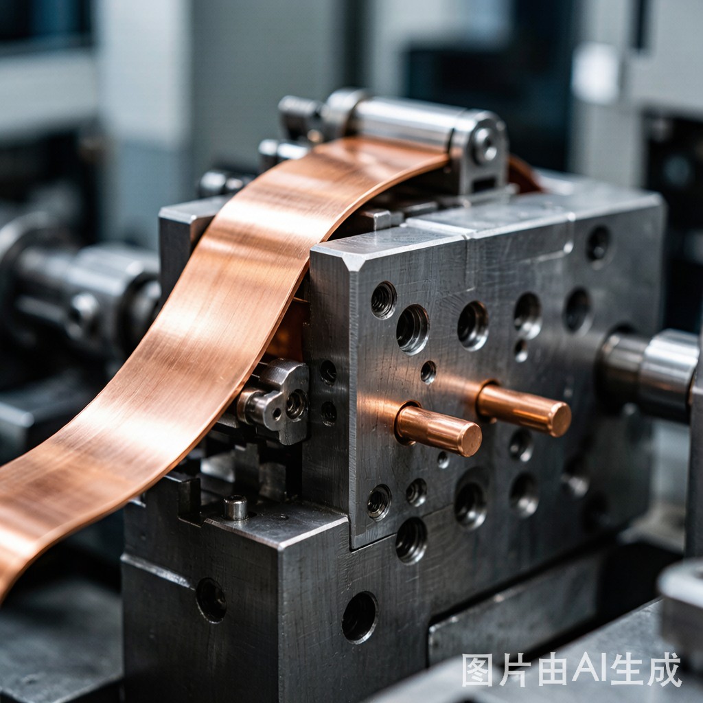
Progressive Die Stamping for SMT Co
ector Pins
SMT (Surface Mount Technology) co
ector pins — the tiny copper alloy terminals that bridge PCBs to external interfaces — are manufactured almost exclusively by progressive die stamping. In this process, copper alloy strip (typically C19400, C26800 brass, or C51000 phosphor bronze) feeds through a multi-station die, with each station performing a specific forming operation: blanking, piercing, bending, coining, and severing. A single progressive die may contain 10–25 stations, producing finished pins at rates of 300–800 strokes per minute.
The economic viability of high-volume SMT co
ector production depends directly on tool wear behavior. As punches and die inserts degrade through repeated contact with copper alloy strip, part dimensions drift, burr heights increase, and surface finish deteriorates. Understanding wear mechanisms, predicting wear rates, and implementing maintenance strategies are core competencies for any stamping operation serving the electronics industry.
Tool Wear Mechanisms in Copper Alloy Stamping
Adhesive Wear (Galling)
Adhesive wear — also called galling — is the dominant wear mode in copper alloy stamping. It occurs when copper alloy material transfers onto the tool steel surface under high contact pressure and sliding friction:
- Mechanism: At contact pressures exceeding the softer material’s yield strength, asperities on the copper strip and tool surface weld together momentarily. Continued sliding fractures these micro-welds, transferring copper alloy material onto the tool (tool buildup) or removing tool material (tool wear)
- Copper alloys most prone to galling: Pure copper (C11000) and high-copper alloys (C19400) — their ductility and lack of hard second-phase particles maximize adhesive transfer
- Brass (C26800) behavior: Zinc in brass reduces galling compared to pure copper — zinc oxide forms a semi-lubricating tribofilm at the tool-workpiece interface
- Phosphor bronze (C51000) behavior: Sn content further reduces galling — tin’s low shear strength creates a self-lubricating surface effect
Abrasive Wear
Abrasive wear occurs when hard particles in the copper alloy (Fe dispersoids in C19400, Sn particles in C51000) or hard oxides on the strip surface act as micro-cutting tools against the die steel:
- Two-body abrasion: Hard second-phase particles in the alloy directly gouge the tool surface during sliding contact
- Three-body abrasion: Loose debris particles (oxide fragments, slitting burrs, die wear particles) roll between tool and strip, creating rolling-indentation damage
- Impact: C19400’s Fe-precipitates (5–50 nm, hardness ≈500 HV) cause measurable two-body abrasion on D2 tool steel (hardness ≈600 HV after heat treatment) over thousands of strokes
Fatigue Wear (Punch Chipping)
Progressive die punches experience cyclic loading at every stroke — typically 300–800 cycles per minute. The resulting fatigue can cause:
- Punch edge chipping: Micro-cracks initiate at stress concentration points (punch edge radii <0.05 mm for fine-pitch pins), propagate under cyclic loading, and eventually cause catastrophic edge fracture
- Punch tip cracking: Axial fatigue cracks in punch tips, particularly in piercing punches that must shear through strip and then retract against spring stripper pressure
- Impact severity factor: C19400 (UTS ≈350 MPa H04) generates higher punching force than C26800 brass (UTS ≈300 MPa), accelerating punch fatigue cycles to failure
Tool Steel Selection and Treatment
Common Tool Steels for Copper Alloy Stamping
| Tool Steel | Hardness (HRC) | Wear Resistance | Toughness | Best Application |
|---|---|---|---|---|
| D2 (1.5% C, 12% Cr) | 58–62 | Excellent | Low | Blanking/piercing dies — high wear, low shock |
| A2 (1% C, 5% Cr) | 57–61 | Good | Moderate | Forming/bending stations — moderate wear, moderate shock |
| M2 (0.85% C, 4% Cr, 5% Mo, 6% W, 2% V) | 62–65 | Very high | Low | Punches for thin strip (<0.15 mm) — maximum hardness needed |
| Carbide (WC-Co) | 70–75 HRA | Extreme | Very low | Long-run blanking inserts (>500K strokes between regrinds) |
| Powder steel (CPM10V) | 60–62 | Very high (10% V carbides) | Moderate | High-volume progressive dies — best balance of wear + toughness |
Surface Treatment Options
Beyond base steel selection, surface treatments dramatically extend tool life:
- TiN coating (2–5 μm): Gold-colored ceramic coating, hardness ≈2300 HV. Reduces galling and abrasive wear by 3–5× compared to uncoated D2. Most cost-effective coating for general copper alloy stamping
- TiCN coating (2–4 μm): Harder than TiN (≈3000 HV), better for abrasive-wear-dominant applications (C19400 with hard Fe-precipitates). Blue-gray color
- AlCrN coating (2–4 μm): Newest generation, hardness ≈3200 HV, excellent oxidation resistance. Best for high-speed stamping where friction heating occurs
- DLC (Diamond-Like Carbon, 1–3 μm): Lowest friction coefficient (μ ≈ 0.1 vs 0.4 for uncoated steel). Best for anti-galling in pure copper stamping, but limited thickness restricts total tool life
- Nitriding (gas nitriding, 0.05–0.15 mm case depth): Not a coating but a diffusion treatment. Increases surface hardness to 65–70 HRC equivalent without dimensional change. Often combined with TiN topcoat (nitrided substrate + TiN = maximum tool life)
Burr Formation and Control
Burr Mechanics in Copper Alloy Stamping
Every stamping operation produces a burr — a thin ridge of displaced material at the sheared edge. Burr height directly correlates with tool wear progression:
- Sharp tool: Burr height 0.02–0.05 mm (acceptable for SMT co
ector pins per IPC-A-610 Class 2)
- Worn tool (200K strokes): Burr height 0.05–0.10 mm — borderline, may require deburring
- Severely worn tool (500K+ strokes): Burr height 0.10–0.20 mm — unacceptable, must regrind or replace punch/die
Burr Height Measurement and Acceptance Criteria
| SMT Pin Application | Max Burr Height | Measurement Method | Frequency |
|---|---|---|---|
| Signal pin (low current) | 0.05 mm | Optical comparator | Every 5K strokes |
| Power pin (high current) | 0.08 mm | Contact micrometer | Every 10K strokes |
| Ground pin (EMI shielding) | 0.10 mm | Visual inspection + gauge | Every 20K strokes |
Burr Control Strategies
- Optimized punch-die clearance: 5–8% of strip thickness for copper alloys (vs 10–15% for steel stamping). Tighter clearance reduces burr height but increases punching force and punch wear rate
- Coined edge stations: Additional coining station after blanking flattens burr to <0.02 mm — adds one die station but eliminates downstream deburring
- Dull punch regrinding schedule: Regrind punches at predetermined stroke intervals (typically 100–200K strokes) before burr height exceeds acceptance limits
- Strip lubrication: Light stamping lubricant (1–3 g/m²) reduces punch-die friction, slowing wear progression and reducing burr growth rate by 20–40%
Maintenance Scheduling and Predictive Wear Models
Stroke-Based Maintenance Intervals
| Maintenance Action | Interval (strokes) | For D2 Tool Steel | For Carbide Inserts |
|---|---|---|---|
| Visual inspection + burr measurement | Every 5K–10K | Required | Required |
| Punch regrind | 100–200K | Every 150K | Every 300–500K |
| Die insert replacement | 200–400K | Every 250K | Every 500K–1M |
| Full die rebuild | 500K–1M | Every 800K | Every 2M |
| Guide pin/bush replacement | 1M–2M | Every 1.5M | Every 3M |
Predictive Wear Modeling
Progressive die wear follows a characteristic three-phase curve:
- Phase 1: Break-in (0–5K strokes): Rapid initial wear as tool surface asperities flatten. Burr height spikes briefly then stabilizes
- Phase 2: Steady-state (5K–300K strokes): Linear wear progression. Burr height increases slowly and predictably. This is the production phase where dimensional stability is maintained
- Phase 3: Accelerated wear (>300K strokes for D2): Wear rate increases as tool surface degradation (micro-cracking, coating delamination) compounds. Burr height accelerates exponentially — this phase signals the need for regrind or replacement
Predictive models use Phase 2 burr height rate (μm per 10K strokes) to calculate the stroke count at which burr height will reach the acceptance limit. This enables maintenance scheduling that prevents quality escapes without u
ecessary premature tool changes.
Strip Material Influence on Tool Wear
Alloy-Specific Wear Rates
| Copper Alloy | Relative Wear Rate (D2, uncoated) | Primary Wear Mechanism | Recommended Tool Treatment |
|---|---|---|---|
| C11000 (pure copper) | 1.0× (baseline — severe galling) | Adhesive (galling) | DLC coating + stamping lubricant |
| C19400 (Cu-Fe) | 1.3× (higher due to Fe abrasion) | Adhesive + abrasive | TiCN or AlCrN + nitrided substrate |
| C26800 (brass) | 0.7× (Zn reduces galling) | Moderate adhesive | TiN coating sufficient |
| C51000 (phosphor bronze) | 0.5× (Sn self-lubricating) | Light adhesive | TiN or uncoated D2 acceptable |
| C7521 (nickel-silver) | 0.9× (Ni increases hardness but maintains ductility) | Mixed adhesive/abrasive | TiCN coating |
Conclusion
Tool wear in progressive die stamping of SMT co
ector pins from copper alloy strip is a multi-mechanism process — adhesive galling dominates for pure copper and high-copper alloys, while abrasive wear from hard second-phase particles (Fe in C19400, Sn in C51000) compounds the damage. The right tool steel selection (D2 for blanking, A2 for forming, carbide for long-run inserts), combined with appropriate surface treatments (TiN/TiCN/AlCrN coatings, nitriding), optimized punch-die clearance (5–8%), and stroke-based maintenance scheduling, transforms tool wear from an unpredictable quality risk into a managed production parameter. For SMT co
ector manufacturers shipping millions of pins per month, investing in carbide inserts and advanced coatings for the highest-wear stations pays for itself within the first 100K strokes through reduced regrind costs, fewer scrap events, and consistent dimensional quality from run to run.



