Introduction
Conformal coating protects SMT assemblies from moisture, dust, chemicals, and electrical creepage. However, the coating only works if it is thick enough to provide reliable coverage without being so thick that it traps heat, obscures markings, or cracks under thermal cycling. Measuring coating thickness accurately is therefore a key quality control step for any electronics manufacturer serving automotive, industrial, or outdoor markets.
Why Thickness Control Is Critical
Too little conformal coating leaves copper traces and solder joints exposed to environmental contaminants. A pinhole or thin area above a high-voltage node can become the starting point for corrosion or dendritic growth. Too much coating adds weight, increases material cost, and can interfere with co
ectors, switches, and heat-dissipating components.
The ideal thickness depends on the coating chemistry. Acrylic, polyurethane, silicone, and parylene coatings each have different dielectric strength, flexibility, and coverage characteristics. A thickness that is optimal for one material may be insufficient or excessive for another. Process validation must therefore define both the target thickness and the acceptable range for each specific material and application.
Non-Destructive Measurement Methods
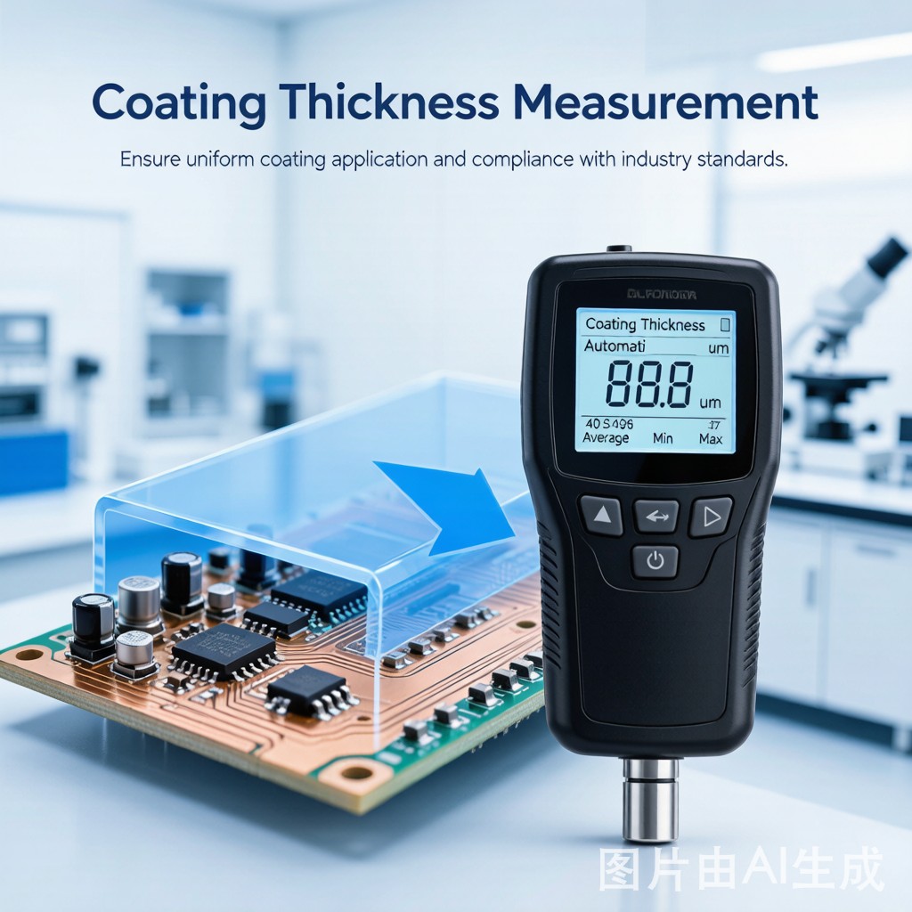
Non-destructive testing is preferred for production inspection because it does not damage the assembly. The two most common methods are eddy current and ultrasonic gauging. Both require calibration on known standards and careful attention to substrate effects.
Eddy current gauges measure the distance between a probe and the conductive copper layer beneath the coating. They work best on flat, metal-backed areas with uniform copper distribution. The instrument calculates coating thickness from the change in induced eddy current response. Accuracy depends on calibration against the actual substrate and coating material, and measurements over large copper pours give more stable readings than measurements over sparse traces.
Ultrasonic gauges send a high-frequency sound pulse through the coating and measure the time delay of the echo reflected from the coating-to-substrate interface. They can measure over non-conductive substrates and complex geometries, but they require good acoustic coupling and are sensitive to coating density and porosity. Air bubbles or uneven surfaces can produce false readings.
Comparison of Measurement Methods
| Method | Type | Best For | Limitations |
|---|---|---|---|
| Eddy Current | Non-destructive | Flat copper areas | Requires conductive substrate |
| Ultrasonic | Non-destructive | Complex shapes | Needs acoustic coupling |
| Cross-Sectioning | Destructive | Calibration and disputes | Slow, requires sample prep |
| Weight Difference | Destructive indirect | Average thickness on coupons | No local thickness data |
Destructive Reference Methods
Cross-sectioning remains the reference method for thickness calibration and for resolving disputes between suppliers and customers. A small section of the coated board is encapsulated in resin, polished, and examined under a microscope. This method shows the exact coating profile over traces, solder joints, and component bodies, including minimum and maximum thickness points.
The main disadvantage of cross-sectioning is that it destroys the sample and provides only local information. It is typically used during process qualification, on witness coupons processed alongside production boards, or when non-destructive readings are questionable.
IPC Standards and Acceptance Criteria
IPC-A-610 and IPC-CC-830 provide widely accepted acceptance criteria for conformal coating. The most common thickness requirements are 25 to 75 µm for acrylic and polyurethane coatings, 50 to 100 µm for silicone, and 12 to 25 µm for parylene. These values refer to the minimum dry-film thickness on critical conductor areas, not just the average over the board.
IPC-CC-830 also defines electrical, adhesion, and environmental tests that coating must pass regardless of measured thickness. A coating that meets the thickness window but fails adhesion or insulation resistance is still unacceptable. For this reason, thickness measurement should be part of a broader qualification protocol that includes visual inspection, adhesion testing, and insulation resistance verification.
Practical Measurement Strategy
A robust inspection plan combines measurement locations, sample size, and calibration discipline. Measurements should be taken on defined test coupons or on production boards in representative areas: over a solid copper pour, between fine traces, and at the edge of a component body. At least five readings per board are typical, with more for high-reliability applications.
Instruments must be calibrated daily using certified thickness standards traceable to the coating and substrate stackup. Operators should record substrate material, copper weight, and coating type because each affects the measurement model. Finally, destructive cross-sections should be performed periodically to confirm that non-destructive gauges remain accurate as processes drift.
Conclusion
Conformal coating thickness measurement is a straightforward quality control task that becomes unreliable without proper method selection, calibration, and standards awareness. By matching the measurement technique to the board geometry, validating against cross-sections, and following IPC acceptance criteria, manufacturers can ensure their SMT assemblies receive the protective coverage they need for long-term field reliability.



