Introduction
The edges of copper strip are easy to ignore, yet they are one of the most common sources of defects in SMT lead frames, co
ector contacts, and stamped terminals. A rough edge or protruding burr can scratch dies, jam feeders, create particles, and compromise the electrical and mechanical performance of finished components. Edge conditioning and burr-free slitting are precision processes designed to give copper strip the clean, rounded, dimensionally stable edges that high-speed SMT production demands.
Why Edge Quality Matters in SMT Components
In progressive die stamping, the strip edge repeatedly engages guide rails, feed rollers, and stripper plates. A sharp or burred edge accelerates wear on these components and generates metallic debris that can lodge in dies or contaminate critical surfaces. For fine-pitch lead frames, even a small edge defect can affect pitch accuracy, coplanarity, and insertion force.
Co
ector manufacturers also care about edge quality because the strip edge often becomes the mating surface or contact shoulder after forming. A burr left on the raw material will translate into a raised feature on the final part, increasing contact resistance, interfering with assembly, or creating a stress concentration point that promotes fatigue cracking.
How Slitting Creates Burrs
Slitting cuts a wide master coil into narrower strips using rotary knives or shear blades. In an ideal shear cut, the blades separate the metal by plastic deformation and fracture, leaving a clean edge with a small burr roll on one side. In practice, burr size depends on blade clearance, blade wear, strip thickness, material hardness, and cutting speed.
Excessive blade clearance allows the metal to tear before shearing, producing a large ragged burr and a pronounced fracture zone. Worn or chipped blades create localized burr peaks. High cutting speeds can generate heat that softens the copper locally, changing its deformation behavior and increasing adhesion to the blade. These effects are especially problematic for thin copper strip below 0.30 mm, where even a 10 µm burr represents a significant percentage of the strip thickness.
Edge Conditioning Methods
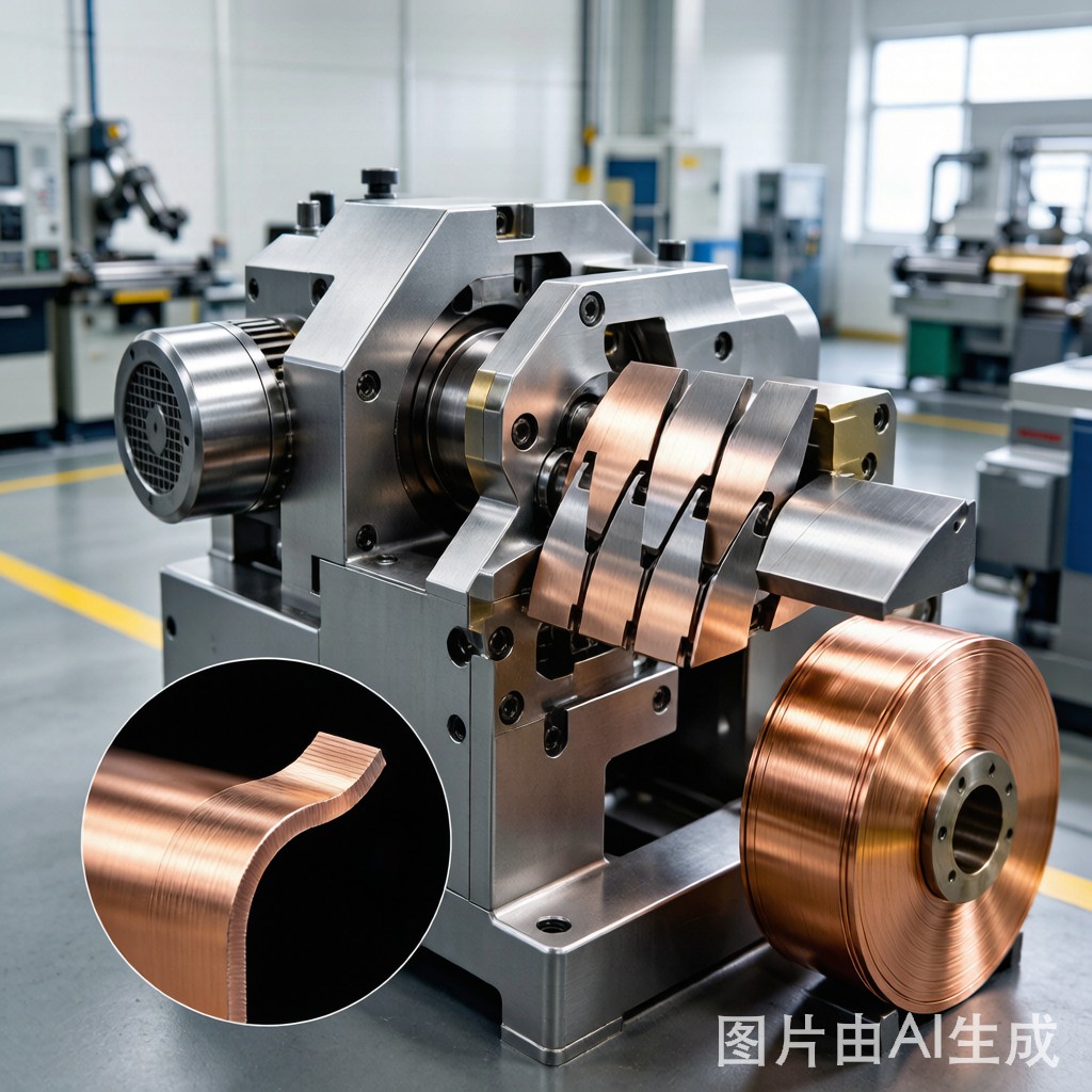
Edge conditioning goes beyond simple slitting to improve the edge geometry and remove burrs. Common methods include edge deburring, edge radiusing, and edge rolling. Each is selected based on the final application and the level of edge refinement required.
Mechanical deburring uses abrasive belts, brushes, or grinding wheels to remove the burr and smooth the edge. This is effective for standard co
ector strip but can round over the edge excessively if not controlled. Edge radiusing uses formed tooling to create a controlled radius along the strip edge, which reduces stress concentration and improves handling. For the most demanding applications, electrochemical or vibratory finishing can polish the edge to a near-mirror finish while maintaining tight dimensional tolerances.
Typical Edge Quality Specifications
| Parameter | Standard Grade | Premium Grade |
|---|---|---|
| Maximum Burr Height | ≤ 25 µm | ≤ 10 µm |
| Edge Radius | 0.05 – 0.15 mm | 0.10 – 0.25 mm |
| Surface Roughness (Ra) | ≤ 1.6 µm | ≤ 0.8 µm |
| Application | General co
ectors | Fine-pitch lead frames |
Inspection and Measurement
Burr height is typically measured with a profilometer, optical comparator, or sca
ing electron microscope for very small features. The measurement is taken perpendicular to the edge surface at the point of maximum protrusion. For production control, many manufacturers use a go/no-go gauge or automated vision system to check 100% of the strip edge.
Edge radius is verified using optical microscopy or contact stylus profilometry. A radius that is too small leaves a sharp edge prone to cracking; a radius that is too large reduces the usable width of the strip and can interfere with tight-pitch stamping layouts. Consistency along the coil length is just as important as the absolute value, since variations can cause intermittent feeding problems.
Process Control Best Practices
Maintaining burr-free edges starts with proper knife setup. Blade clearance should be set according to the strip thickness and copper alloy, typically 5% to 10% of thickness per side. Knives must be inspected and sharpened on a regular schedule, and replacement should not wait for visible defects. Lubrication during slitting reduces heat buildup and blade adhesion, especially for soft a
ealed copper.
Tension control during recoiling also affects edge quality. Uneven tension can stretch the strip locally, distorting the edge and creating camber. Using back tension and properly aligned coil handling equipment keeps the strip stable through the slitting line. Finally, packaging with edge protectors and interleaf paper prevents handling damage between slitting and stamping.
Conclusion
Copper strip edge conditioning and burr-free slitting are critical upstream processes that determine the success of downstream SMT stamping and assembly. By controlling blade condition, clearance, and tension, and by applying the right deburring or radiusing method, manufacturers can deliver strip with edges that feed smoothly, form cleanly, and meet the exacting requirements of modern lead frames and co
ectors.



