## Joining Challenges in Copper SMT Lead Frame Manufacturing
SMT lead frames—the thin metallic substrates that co
ect semiconductor dice to printed circuit boards—are predominantly manufactured from copper alloys: C11000 (ETP copper), C19400 (iron-modified copper), and C19210 (copper-iron-phosphorus). These alloy strips, typically 0.10–0.25 mm thick, must be joined at multiple process stages: i
er lead-to-die pad bonding, outer lead tab-to-tab welding for gang bonding, and lead frame-to-substrate interco
ects in quad flat no-lead (QFN) and land grid array (LGA) packages.
The joining challenge is formidable. Copper alloys have high thermal conductivity (385–401 W/m·K for C11000, 260–280 W/m·K for C19400), which rapidly dissipates welding heat away from the joint zone. This demands concentrated energy input with minimal thermal spread—exactly the conditions where welding method selection becomes critical. Laser welding and resistance welding are the two dominant joining technologies, each exploiting different physics to achieve reliable copper joints.
## Laser Welding: Precision Energy Delivery
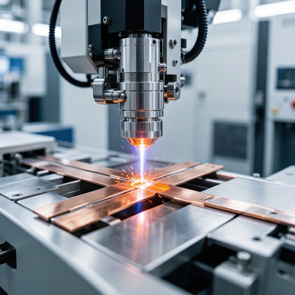
Laser welding delivers focused photon energy through a coherent beam, typically using pulsed Nd:YAG (1064 nm) or fiber lasers (1070 nm) for copper strip applications. The key advantage is spatial precision: beam diameters of 0.2–0.8 mm concentrate energy into a spot smaller than the lead frame tab width, enabling welds at precise locations without affecting adjacent structures.
### Heat Input and Penetration Control
Pulsed laser welding parameters for copper strip are defined by peak power, pulse duration, and pulse shape. For 0.15 mm C19400 lead frame material, typical parameters include:
| Parameter | Range | Effect |
|———–|——-|——–|
| Peak Power | 500–2000 W | Controls melt pool depth |
| Pulse Duration | 2–10 ms | Governs thermal penetration |
| Pulse Frequency | 10–50 Hz | Affects weld overlap |
| Spot Diameter | 0.3–0.6 mm | Defines joint width |
| Shield Gas | Argon + 2% H₂ | Prevents oxidation, stabilizes plasma |
The high peak power of pulsed lasers overcomes copper’s reflectivity challenge—at 1064 nm, polished copper reflects approximately 95% of incident energy. Modern fiber lasers address this through pulse shaping: a low-power pre-pulse creates an absorbing surface condition (oxidation or roughening), followed by the high-power main pulse that delivers the welding energy. This two-step approach reduces the effective reflectivity from 95% to approximately 30–40% at the weld onset.
### Joint Characteristics
Laser welds in thin copper strip produce narrow, deep penetration profiles with aspect ratios (depth/width) of 2:1 to 4:1. For 0.15 mm C19400 strip, full penetration welds typically measure 0.3–0.5 mm wide at the top surface, with minimal heat affected zone (HAZ) extending only 0.1–0.2 mm beyond the weld boundary. This confined thermal footprint preserves the mechanical properties and surface finish of adjacent lead frame areas—critical for subsequent die attach and wire bonding operations.
## Resistance Welding: Current-Based Heat Generation
Resistance welding generates heat through Joule heating (I²R) at the interface between two copper strips pressed together under controlled electrode force. The welding current passes through the stacked workpieces, with maximum resistance—and therefore maximum heating—at the contact interface where microscopic surface asperities create localized high-resistance paths.
### Process Parameters for Copper Alloys
Copper’s high electrical conductivity (IACS 101% for C11000, 50–60% for C19400) presents a dual challenge: low bulk resistance reduces available Joule heating, while high thermal conductivity rapidly conducts generated heat away from the joint. Resistance welding copper therefore requires very high current, short weld times, and precisely controlled electrode force:
| Parameter | C11000 ETP | C19400 Fe-Cu | C19210 Cu-Fe-P |
|———–|———–|————-|—————-|
| Weld Current | 8–12 kA | 5–8 kA | 4–7 kA |
| Weld Time | 2–6 cycles (33–100 ms) | 4–10 cycles | 3–8 cycles |
| Electrode Force | 40–80 N | 30–60 N | 25–50 N |
| Electrode Material | WC-Cu composite | WC-Cu / Mo | WC-Cu / Mo |
| Nugget Diameter | 0.4–0.8 mm | 0.5–1.0 mm | 0.5–1.0 mm |
C19400 and C19210 alloys are significantly easier to resistance weld than C11000 because their higher bulk resistance (lower IACS conductivity) generates more Joule heating per unit current. This is reflected in the lower required current levels and wider nugget formation. For C11000, the combination of minimal bulk resistance and extreme thermal conductivity makes consistent nugget formation challenging—electrode sticking and surface damage are common production issues.
### Joint Profile and HAZ
Resistance weld nuggets in thin copper strip are elliptical in cross-section, with aspect ratios typically 1.5:1 to 2:1 (width greater than depth). For 0.15 mm C19400, nugget dimensions are approximately 0.6–0.8 mm diameter × 0.12–0.14 mm depth (near-full penetration). The HAZ extends 0.3–0.5 mm beyond the nugget boundary—significantly wider than laser welds—due to the radial heat flow pattern inherent in resistance welding geometry.
## Comparative Analysis: Laser vs Resistance Welding
### Thermal Distortion
Lead frame dimensional stability directly affects die placement accuracy and wire bonding yield. Laser welding’s concentrated heat input produces minimal distortion: measured warpage on 0.15 mm C19400 tab joints is typically <0.02 mm over a 25 mm lead frame section. Resistance welding, with its wider thermal spread, produces 0.05–0.12 mm warpage over the same distance—a critical difference for fine-pitch QFN packages where lead coplanarity tolerance is ±0.05 mm per JEDEC MO-220.
### Joint Strength Comparison
Shear strength testing of tab-to-tab welds reveals the following results for 0.15 mm strip:
| Weld Method | C11000 Shear (N) | C19400 Shear (N) | C19210 Shear (N) |
|————-|——————|——————|——————|
| Laser (pulse) | 8–12 | 15–22 | 18–25 |
| Resistance (spot) | 6–10 | 12–18 | 14–20 |
| Baseline (parent metal) | 220 MPa YS | 290 MPa YS | 310 MPa YS |
Laser welds consistently achieve 10–25% higher shear strength than resistance welds across all three copper alloys. The strength advantage derives from the narrower, deeper penetration profile that preserves more parent metal cross-section and produces a more homogeneous fusion zone with finer grain structure (cooling rates 10⁴–10⁵ °C/s for laser vs 10³–10⁴ °C/s for resistance).
### Production Throughput and Cost
Resistance welding excels in high-volume production scenarios. A single resistance weld cycle completes in 33–100 ms, with electrode positioning and approach adding 50–100 ms—total cycle time per joint of 0.1–0.2 s. Modern projection welding systems can join 40–60 lead frame tabs simultaneously in a single pulse, achieving gang bonding throughput of 20–30 lead frames per minute.
Laser welding, while slower per joint (0.2–0.5 s including beam positioning), offers flexibility advantages: programmable weld locations, multi-pass capability for thick joints, and no electrode wear or maintenance. For low-volume, high-mix production with frequent design changes, laser welding's tooling-free approach reduces changeover cost from $2,000–$5,000 per product (new resistance welding electrodes and fixture) to near-zero (updated CNC program only).
## Practical Selection Guidelines
Choose laser welding when:
– Lead frame thickness ≤ 0.20 mm with tight coplanarity requirements
– Joint locations vary across product families (programmable flexibility)
– Alloy is high-conductivity C11000 (resistance welding struggles)
– Adjacent structures are heat-sensitive (die attach adhesive, surface coatings)
– Production volume is low-to-medium with frequent design changes
Choose resistance welding when:
– Gang bonding multiple tabs simultaneously (40–60 joints per pulse)
– High-volume, single-product production lines (>10,000 units/hour)
– Alloy is C19400 or C19210 (inherent resistance weldability advantage)
– Joint strength requirements are moderate (not structural load-bearing)
– Equipment capital cost must be minimized (resistance welders 30–50% cheaper)
## Conclusion
Both laser and resistance welding produce reliable joints in copper SMT lead frame alloys, but their thermal physics, joint geometry, and production economics differ fundamentally. Laser welding delivers precision and flexibility at the cost of throughput; resistance welding delivers speed and economy at the cost of thermal spread. The optimal choice depends on your alloy, pitch requirements, production volume, and the dimensional tolerance window your package specification allows. For most modern QFN/LGA lead frame applications with fine-pitch requirements and mixed alloy usage, laser welding is increasingly the preferred technology—though resistance projection welding remains dominant in high-volume gang bonding operations.



