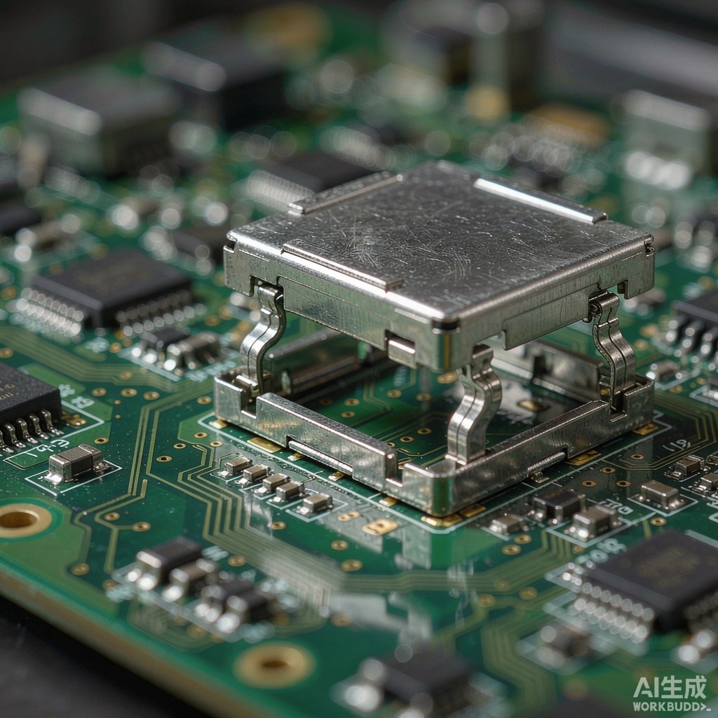
Board-level EMI shields come in two dominant constructions: soldered one-piece or two-piece cans attached in the reflow oven, and clip-on cans that press onto soldered or surface-mounted frames and can be lifted off for rework. The choice ripples through PCB layout, assembly yield, service strategy, and unit cost — and the right answer changes with product maturity. Here is how the trade-offs actually break down.
How Each Construction Works
Soldered Shield Cans
A one-piece can (or a frame-plus-lid two-piece set) is placed over the protected region and reflowed along its wall to a ground trace perimeter on the PCB. The solder joint provides both mechanical retention and the electrical seam. Two-piece versions allow the lid to be removed after soldering the frame, but the frame remains permanently attached. Soldered cans are the default for high-volume consumer boards because placement and reflow add almost no process cost.
Clip-On Shield Cans
A solderable frame (or surface-mount clips) is reflowed to the PCB first. The can itself is a stamped part with spring fingers or gull-wing walls that press onto the frame at final assembly — after reflow, after ICT, sometimes even at final test. Electrical contact is made through spring pressure along the frame top. The can is removable without heat, which is the entire point.
Shielding Effectiveness: Small but Real Differences
A well-formed soldered seam is continuous metal-to-metal and offers the best inherent seam performance, especially above 1 GHz where any gap or intermittent contact becomes an ante
a. Clip-on cans depend on contact pressure at discrete finger points; performance is typically 5–15 dB below soldered equivalents in the 1–6 GHz range, and the gap between fingers can resonate. In practice, clip-on cans still deliver 40–70 dB of shielding in that band — adequate for most FCC/CISPR 32 margins — but designs fighting a specific radiated emission with little margin should default to soldered. Contact corrosion is a long-term factor: fretting and oxidation at finger contacts can raise impedance over years; tin-plated contacts on tin-plated frames are acceptable, while mixed tin/gold systems need design care.
PCB Footprint and Layout Rules
Soldered Cans
Wall lands consume board area around the perimeter, and castellations or via stitching for ground continuity add layout effort. Wall width is typically 0.4–0.8 mm plus land. Clearance for inspection under the can is impossible once soldered — AOI must occur before can placement, or X-ray is needed.
Clip-On Cans
The frame footprint is similar, but the removable can enables post-assembly visual inspection, debug, and firmware-less hardware rework. Keep-out for spring finger compression (typically 0.3–0.5 mm deflection travel) must be respected by nearby tall components. Clip-on cans also tolerate slight frame coplanarity error better than a soldered seam tolerates warp.
Rework and Field Service Economics
The decisive question: how often will someone need to open the can? During development, the answer is constantly — RF tuning, ante
a matching, component swaps. Clip-on cans save hours per iteration. In production, rework frequency drops to ppm levels, and soldered cans are fine. In field service, the picture reverses again: products with user-serviceable modules, radio certification variants (the same PCB with different RF front ends), or region-specific configurations benefit enormously from a removable can — one PCB, multiple shield configurations, no BGA rework station at the service depot.
Rework Cost Reality
Removing a soldered can requires localized heating, risks disturbing nearby passives, and typically destroys the can (a $0.05–0.30 part) plus possible pad damage. Clip-on removal is seconds and leaves everything reusable. For NPI runs under a few hundred units, the avoided rework alone usually pays the clip-on premium.
Cost Structure at Volume
At high volume, soldered one-piece cans win on BOM (no second hardware step) and line time. Clip-on systems cost more in two pieces (frame + can), an extra placement operation, and contact-plating quality. Typical crossover: above roughly 100k units per year with stable design, soldered is cheaper; below that, or with any meaningful design churn, clip-on’s flexibility dominates. Stamped tooling for either style is modest ($2k–8k per size), but each shield size is a new tool — standardizing on a few frame sizes across product families amortizes NRE meaningfully.
A Decision Framework
- Prototype/NPI: clip-on. Iterate freely, inspect freely.
- High-volume consumer, fixed RF design: soldered one-piece. Lowest cost, best high-frequency seam.
- Multi-variant radios on one PCB: soldered frame + removable lid, or clip-on can per variant.
- Tight emission margin at >3 GHz: soldered, with a continuous seam and verified via stitching.
- Field-configurable or serviceable hardware: clip-on, with contact material spec and retention-force verification on the test plan.
Whichever you choose, the ground perimeter under the wall does the real work: stitch it with vias at λ/20 spacing or less for your highest concern frequency, and no can construction will save a poor ground. Get the foundation right first, then pick the construction that fits your lifecycle.



