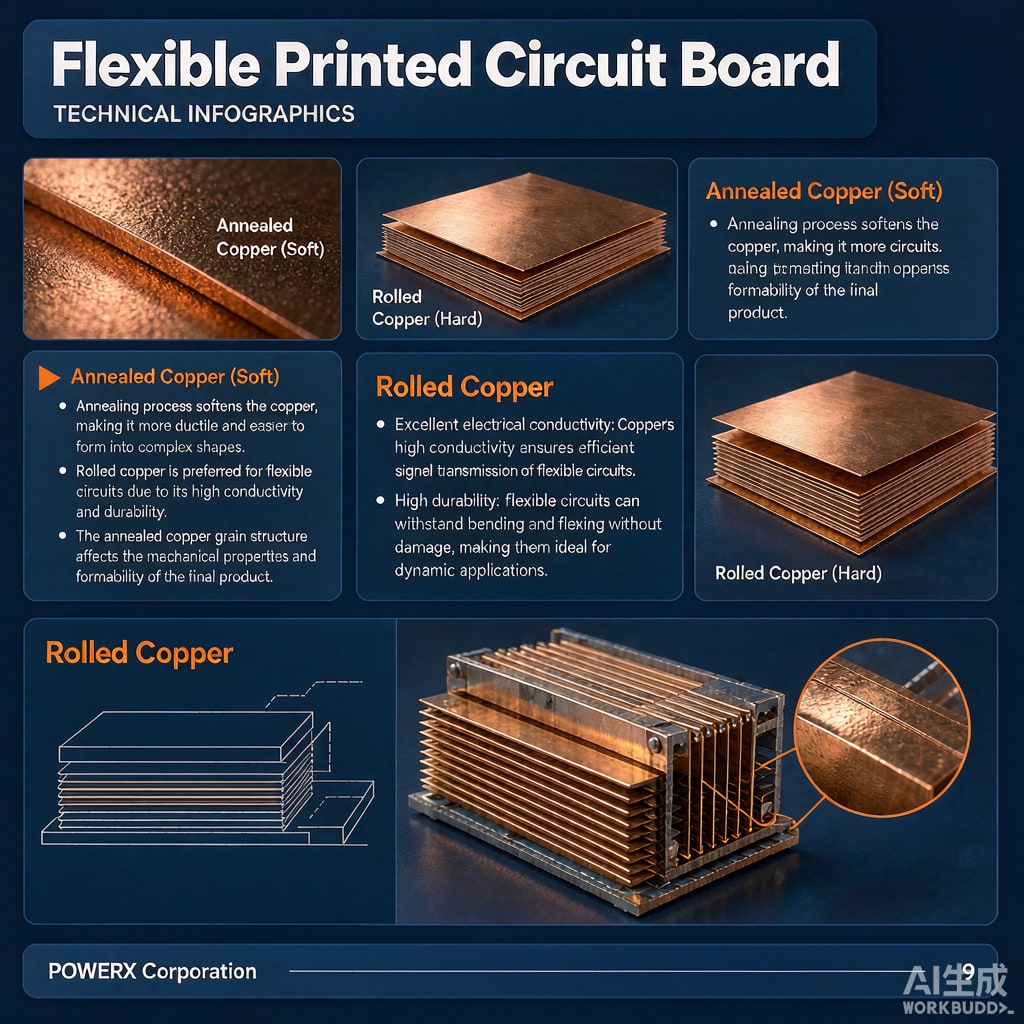
Flexible printed circuits (FPC) live and die by copper foil selection. The same 18 µm (½ oz) foil can survive 100,000 bend cycles in one construction and crack after 5,000 in another, purely because of how the copper was manufactured. Buyers comparing quotes for flex circuits, flex-rigid boards, or dynamic ante
a cables should understand the difference between rolled a
ealed (RA) copper foil and electrodeposited (ED) copper foil before specifying. This guide explains the metallurgy, the measurable differences, and how to choose.
Two Manufacturing Routes, Two Grain Structures
Electrodeposited (ED) Foil
ED foil is grown electrolytically: copper ions plate onto a rotating titanium drum, building a columnar grain structure perpendicular to the foil surface. The drum side is smooth; the bath side is roughened by chemical or electrolytic treatment to improve adhesion to the polyimide or adhesive layer. ED foil is the default for rigid PCBs and for static flex applications because it is inexpensive, dimensionally consistent, and available in thin gauges down to 9 µm.
Rolled A
ealed (RA) Foil
RA foil starts as thick copper sheet and is progressively rolled down to 9–35 µm, then a
ealed. Rolling elongates the grain structure parallel to the foil plane, producing a horizontally oriented, fibrous microstructure. That orientation is the key: when the foil is bent, the elongated grains can slide past each other and absorb strain, rather than failing along vertical columnar boundaries.
Ductility and Bend Life: The Decisive Numbers
Measured elongation at break tells most of the story. Standard ED foil shows roughly 5–12% elongation; high-ductility (HD) ED foil reaches 15–20% after a
ealing; RA foil typically delivers 20–45%, with the highest values after full a
eal. In dynamic flex testing (e.g., IPC-TM-650 method 2.6.3 bending around a defined mandrel), RA foil constructions routinely achieve 5–10× the cycles of equivalent ED constructions.
Where Each Wins
- Static flex: bend-to-install, then never flexed again — ED foil is sufficient and cheaper. Most flex-rigid interco
ects fall here.
- Dynamic flex: hinge cables in laptops, camera modules, sliding assemblies, folding devices — RA foil is effectively mandatory. Specify it in the fab drawing, not the fab’s default.
- Fine-line etch: below 75 µm line/space, the smoother drum side of ED foil (Ra often 1–2 µm treated side vs 0.3–0.5 µm untreated) helps etch definition. RA foil’s rolling marks run parallel to the grain direction and must be aligned with the etch direction.
Surface Roughness, Adhesion, and Signal Loss
ED foil’s roughness is a feature for adhesion and a liability for high-speed signals. Skin effect at multi-gigahertz frequencies forces current into the rough foil surface, increasing conductor loss; treated ED foil can add measurable insertion loss versus RA at frequencies above about 5 GHz. Conversely, RA foil’s smooth profile offers lower adhesion peel strength (typ. 0.9–1.3 N/mm vs 1.4–1.8 N/mm for treated ED), so bondply selection and coverlay lamination pressure need review. For controlled-impedance flex, note that roughness also shifts effective conductor thickness, so impedance modeling should use the actual foil type.
Thickness, Temper, and Grain Direction on the Drawing
Specify Four Things
- Foil type and thickness: e.g., “RA copper, 18 µm, 1/2 oz equivalent.” Do not let “½ oz” alone stand for the spec.
- Grain direction: for RA foil, orient the grain axis along the bend axis requirement — bending across the grain direction sharply reduces bend life. Fab drawings should call out bend axis vs grain orientation.
- A
eal condition:
hard-rolled RA foil loses the ductility advantage; specify fully aealed temper for dynamic applications.
- Bend radius rule: for dynamic flex, keep the neutral-axis bend radius at 100× total flex thickness as a conservative baseline (single-layer can go lower); for static flex, 10–20× is common practice.
Cost and Sourcing Considerations
RA foil typically carries a 20–60% premium over ED in equivalent thickness, and thickness options are narrower (commonly 9, 12, 18, 35 µm). Lead times can be longer because RA volumes are smaller. For buyers consolidating copper foil and copper strip purchases, note that the same rolling-and-a
ealing metallurgy appears in thin copper strip used for EMI fingers, gaskets, and stamped flex interposer contacts — aligning specifications across those purchases simplifies incoming inspection.
Receiving Inspection Checks
- Certificate should state foil type (RA/HD-ED/ED), thickness, and tensile/elongation data. Reject generic “copper foil” C of As.
- Peel strength after coverlay lamination (IPC-TM-650 2.4.9) should meet your drawing, typically ≥1.0 N/mm for static, ≥0.8 N/mm acceptable for dynamic with strain-relief design.
- For dynamic parts, request the fab’s bend-cycle test report at your actual radius and thickness, not a datasheet generic.
A Practical Selection Workflow
Step 1: Classify the application — static, dynamic (<1,000 cycles), or dynamic (>1,000 cycles). Step 2: Default to ED for static, HD-ED for mild dynamic, RA for true dynamic flex. Step 3: For signals above 5 GHz or long parallel runs, evaluate RA for loss reasons even in static designs. Step 4: Fix grain direction, bend radius, and temper on the drawing. Step 5: Confirm peel strength and cycle test data at incoming. This takes minutes per part number and eliminates the most common field failure mode in flex assemblies — foil fatigue cracking at the neutral-axis misalignment.



