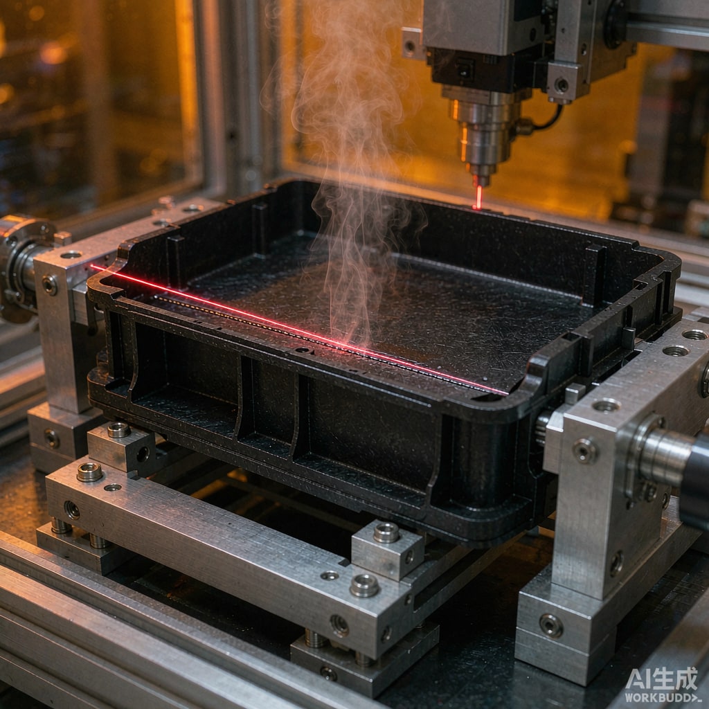
The Seal Problem Laser Welding Solves
An IP67 enclosure built with screws and a compressed gasket has four failure points per screw boss and one continuous failure line around the gasket. Gaskets take compression set, screws relax, and the screw holes themselves are leak paths that must be sealed separately. Ultrasonic welding is faster but struggles with glass-filled resins and large, non-planar seams.
Laser transmission welding solves all three: it produces a continuous hermetic seam, generates no particular debris, works with glass-filled material at reduced but usable settings, and completes a 400 mm perimeter in one to three seconds with a sca
ing head. The price is that it will only work if the two halves of the housing are optically and thermally matched. That decision is made at the pellet specification stage, not at the machine.
The Transmission and Absorption Pair
Standard two-layer welding
One half is transmissive: natural, unpigmented, low-additive resin that lets 980 nm diode laser energy pass through. The other half is absorptive: the same base resin loaded with 0.1 to 0.5 wt% carbon black. The beam passes through the transmissive part, hits the absorbent interface, converts to heat, and conduction melts both surfaces into a weld zone 0.5 to 2 mm deep.
The transmission requirement is the one that gets missed. A 2 mm wall of natural PA66 transmits roughly 40 to 55% at 980 nm. Add 30% glass fiber and scattering drops that to 5 to 15%. At that level you can still weld, but you need higher power density and a longer dwell, and the coupling window narrows sharply.
Clear-to-clear welding
Where both halves must be transparent or the same color, 2 µm thulium fiber lasers replace 980 nm diodes. At 2 µm the absorption mechanism is intrinsic to the polymer rather than dependent on a pigment, so two identical natural parts can be welded. It is slower and the equipment is more expensive, but it removes the color constraint entirely.
Absorber choice beyond carbon black
Carbon black is cheap and effective but locks the part into a black or dark color. Alternatives include near-infrared absorbing dyes (allowing light-colored parts) and clear absorber layers applied as a thin coating at the joint. Both cost more and both need validation of food-contact and RoHS compliance separately.
Resin Selection by Application
PA6 and PA66, glass filled
The workhorse for automotive and industrial housings. Good weld strength, but hygroscopic: moisture above 0.1% flashes to steam in the weld zone and produces voids and pinholes. Dry 4 hours at 80°C or 2 hours at 100°C in a desiccant dryer, and weld within two hours of drying unless the parts go into sealed trays.
PC and PC/ABS
Excellent transmission and good toughness, which is why most consumer electronics use it. The complication is stress cracking: laser welding leaves a hot, constrained weld zone, and molded-in stress plus the wrong mold release agent produces crazing within days. Specify stress-relieved molding and a release agent compatible with the resin.
PBT, PET and PPS
For under-hood and high-temperature electronics. PPS welds reliably at 260°C-plus service temperatures and resists automotive fluids, but its high crystallinity makes the process window narrow. PBT is more forgiving but hydrolyzes if over-dried, so drying at 120°C for more than about 4 hours is counterproductive.
What glass fiber really does
Glass does more than scatter light. Fibers at the weld interface reduce the effective polymer-to-polymer contact area, so weld strength in 30% GF material is typically 60 to 75% of the unfilled value even with optimal parameters. If the joint is structural, design for it from the start: add a mechanical interlock or a longer weld flange rather than relying on weld strength alone.
Joint Geometry
Lap joint, not butt joint
A butt joint has almost no surface area for the melt to flow into and produces weak, leaky welds. A lap joint with a 0.8 to 1.5 mm overlap gives the melt a defined path and tolerates small misalignment. The transmissive part should be on top, with the laser entering through it.
Gap and clamp force
The two surfaces must be in intimate contact before the beam arrives. Any gap greater than 0.1 to 0.2 mm means the beam has to bridge air, which causes burning on the transmissive side and incomplete melting at the interface. Clamp at 0.3 to 1.0 MPa with a fixture that presses within 3 mm of the weld line; clamping far away lets the flange bow.
Energy directors and ribs
Unlike ultrasonic welding, laser welding does not need a triangular energy director. A small rib (0.3 mm tall, 0.5 mm wide) at the joint does help: it concentrates the first melt, provides collapse allowance, and gives a visible witness line for quality inspection.
Weld depth and flash control
Weld depth below 0.4 mm leaks under pressure; above 2.5 mm the transmissive part starts to heat through and you get surface marking. Keep to 0.6 to 1.5 mm for most housings, and design a flash groove if cosmetic appearance matters.
Process Window Basics
Three parameters matter: power density at the interface, scan speed, and clamp pressure. Quasi-simultaneous welding, where the beam traces the entire contour at high speed repeatedly while power ramps down, is the standard for long seams because it heats the whole joint uniformly and allows collapse monitoring. Contour welding, tracing the seam once, works for small parts and short cycles.
Two online monitoring signals are worth specifying: pyrometry at the weld zone and collapse distance measurement. A collapse of 0.1 to 0.3 mm per joint is a good proxy for complete melting, and it catches the single most common defect, a cold weld caused by contamination or a clamp fault.
Validation: Leak, Strength, and Aging
- Leak. For IP67, a pressure decay or bubble test at 0.3 to 0.5 bar is adequate. For IP68, use helium mass spectrometry with an acceptance limit around 1×10⁻⁶ mbar·L/s.
- Strength. Peel or tensile test per ISO 527 on coupons cut from production parts, not from plaques. Target 60 to 90% of bulk resin strength depending on glass content.
- Thermal cycling. −40 to +85°C for 100 cycles, then re-test leak. The weld zone sees the CTE mismatch between filled and unfilled halves, which is the real long-term risk.
- Chemical exposure. Sunscreen, hand sanitizer, automotive fluids. Sealed housings fail at the weld line, not through the wall, when attacked by solvents.
Design for Disassembly and Recycling
A laser-welded housing is not serviceable. If the product needs battery replacement or field repair, weld only part of the perimeter and use a mechanical latch for the rest, or design a sacrificial break line with a replacement cover in the service kit. For end-of-life, welded monomaterial housings are actually easier to recycle than gasket-and-screw assemblies, provided both halves are the same resin grade and the carbon black content stays within the recycler’s tolerance.
Pellet Specification Checklist
- Both halves from the same base resin grade, differing only in absorber content.
- Transmission measured on a molded 2 mm plaque at 980 nm, not taken from a datasheet.
- Glass content stated explicitly, with weld strength data at that content.
- Moisture specification and drying curve supplied with the lot.
- Mold release and any internal lubricant confirmed laser-compatible.
- Color masterbatch screened for NIR absorption; many organics absorb at 980 nm and will ruin the transmissive half.



