Every shielded enclosure that dissipates power faces the same contradiction: it needs a hole to breathe, and the hole is an ante
a. The ventilation aperture is usually the single largest shielding defect in a well-designed metal enclosure — larger than any seam, larger than any co
ector gasket. Getting the airflow-versus-leakage trade-off right is a discipline of its own, and it is where many thermal designs quietly break EMC compliance.
The Physics of a Leaky Hole
An aperture begins to leak significantly when its largest dimension approaches half a wavelength of the frequency of interest. For a slot or hole of length L, the first resonance occurs near λ/2, so a 60 mm opening starts to be a real problem around 2.5 GHz.
Shielding effectiveness of a single aperture
A widely used engineering approximation for a single aperture, valid for the far field and L < λ/2, is:
SE (dB) ≈ 20 log₁₀(λ / 2L)
For 1 GHz (λ = 300 mm) and a 30 mm opening, that gives roughly 14 dB — inadequate for most EMC limits. Shrink the opening to 5 mm and you get about 30 dB. This is the entire rationale for honeycomb: many small apertures replace one large one.
Array behaviour
An array of n identical apertures does not help as much as intuition suggests. The array behaves roughly like a single aperture of the same total area, plus an averaging effect across the array spacing. Practical guidance: keep cell size small and the array’s overall dimensions manageable. A honeycomb panel 300 mm × 300 mm with 3.2 mm cells outperforms a 300 mm × 300 mm perforated panel with 8 mm holes by 15–20 dB in the 1–6 GHz band.
Vent Options and Their Numbers
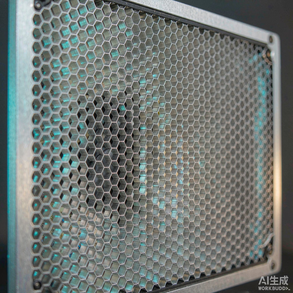
Honeycomb panels
Aluminium or steel foil honeycomb with cell size 1.6–6.4 mm, foil thickness 0.025–0.1 mm, and depth typically 6–25 mm. Cell depth matters: a honeycomb behaves like a short waveguide below cutoff, and greater depth improves attenuation. Typical shielding effectiveness for a 6.4 mm cell, 12 mm deep panel is 40–55 dB from 100 MHz to 1 GHz, falling to 30–40 dB at 6 GHz. Standard cells include 3.2, 4.8, and 6.4 mm.
Airflow penalty is modest: an open-area ratio of 85–95% translates to a pressure-drop multiplier of roughly 1.1–1.3× versus an open hole, depending on depth and cell size. That is usually acceptable.
Perforated metal and expanded mesh
Perforated plate with 1–3 mm holes gives good shielding but a higher airflow penalty and higher weight. Expanded metal mesh is cheaper and lighter but has a worse open-area ratio for the same attenuation and is harder to bond reliably at the frame. Fine mesh screens can reach 60 dB but clog with dust and demand a filter, which reintroduces costs.
Finger-stock frames around vents
A removable vent panel needs a conductive gasket or finger stock around its perimeter, or the panel’s own seam becomes the dominant leak. Never evaluate the vent in isolation from its mounting.
The Airflow Side of the Trade-Off
Adding a vent is not free thermally. Pressure drop scales roughly with the square of velocity, and the fan operating point moves along its curve.
Practical workflow
- Start from the required volumetric flow: heat load divided by allowable temperature rise, adjusted for air density at altitude and tropical ambient.
- Estimate the system impedance of the full air path — inlet vent, internal obstructions, heatsink fins, outlet vent. The vent is usually one term among several.
- Select fan at the resulting operating point, not at free delivery.
- Then check the chosen vent’s attenuation at the highest frequency that matters — typically the highest clock harmonic or radio band you must meet.
Two design rules save iterations. First, place inlet and outlet vents so air crosses the hot components rather than short-circuiting across the top of the enclosure. Second, make the outlet vent area at least as large as the inlet; asymmetric venting pushes fan operation toward stall.
When Honeycomb Is Not Enough
For enclosures that must meet tight limits above 6 GHz or must resist intentional interference, three escalation paths exist.
1. Waveguide-below-cutoff air cha
els
Route cooling air through a long, narrow cha
el rather than a direct aperture. A cha
el whose width is below the cutoff dimension for the frequency of interest attenuates strongly. This is standard practice in shielded racks and high-power RF cabinets, at the cost of significant pressure drop.
2. Screen-over-honeycomb hybrid
A fine conductive mesh bonded over a honeycomb panel adds 10–20 dB at high frequency with a modest airflow cost. Watch dust accumulation and specify a serviceable filter.
3. Sealed enclosure with heat pipes or a cold plate
If the EMC requirement is severe and the heat load is concentrated, eliminate the air path entirely and move heat to an external heatsink through a sealed wall. This removes the ventilation problem from the EMC review altogether and is often the cheapest route for outdoor or high-IP enclosures.
Materials, Corrosion and Grounding
Aluminium honeycomb bonded into a painted steel enclosure is a galvanic couple waiting for humidity. In coastal Southeast Asian installations, specify a conductive conversion coating or nickel plating on the aluminium, or use aluminium throughout. Bond the vent panel to the enclosure with a gasket that carries current across the full perimeter — a vent held by four screws with no gasket is effectively an open slot with decorative cells in it.
Inspection points
- Measure DC bond resistance from vent frame to enclosure wall; target well under 10 mΩ.
- Check that no paint or anodising sits between mating surfaces.
- Verify the cell foil is not crushed at the mounting flange — crushed cells open the aperture.
A Selection Sequence That Works
Define the highest frequency that must be attenuated and the required dB at that frequency. Compute the maximum allowable aperture dimension from SE ≈ 20 log(λ/2L). Choose the vent type whose cell size beats that dimension with margin. Compute the pressure drop at design flow and confirm the fan still delivers the required cooling. Verify perimeter bonding. Then, if possible, test the actual assembly in a pre-compliance setup — vent behaviour interacts with enclosure resonances in ways that spreadsheet estimates miss.
The trade-off is real, but it is not mysterious. Small cells, adequate depth, a properly bonded frame, and a fan selected at the true operating point will satisfy both the thermal engineer and the EMC lab. The failures come from treating the vent as a mechanical afterthought instead of a designed electromagnetic and aerodynamic component.



