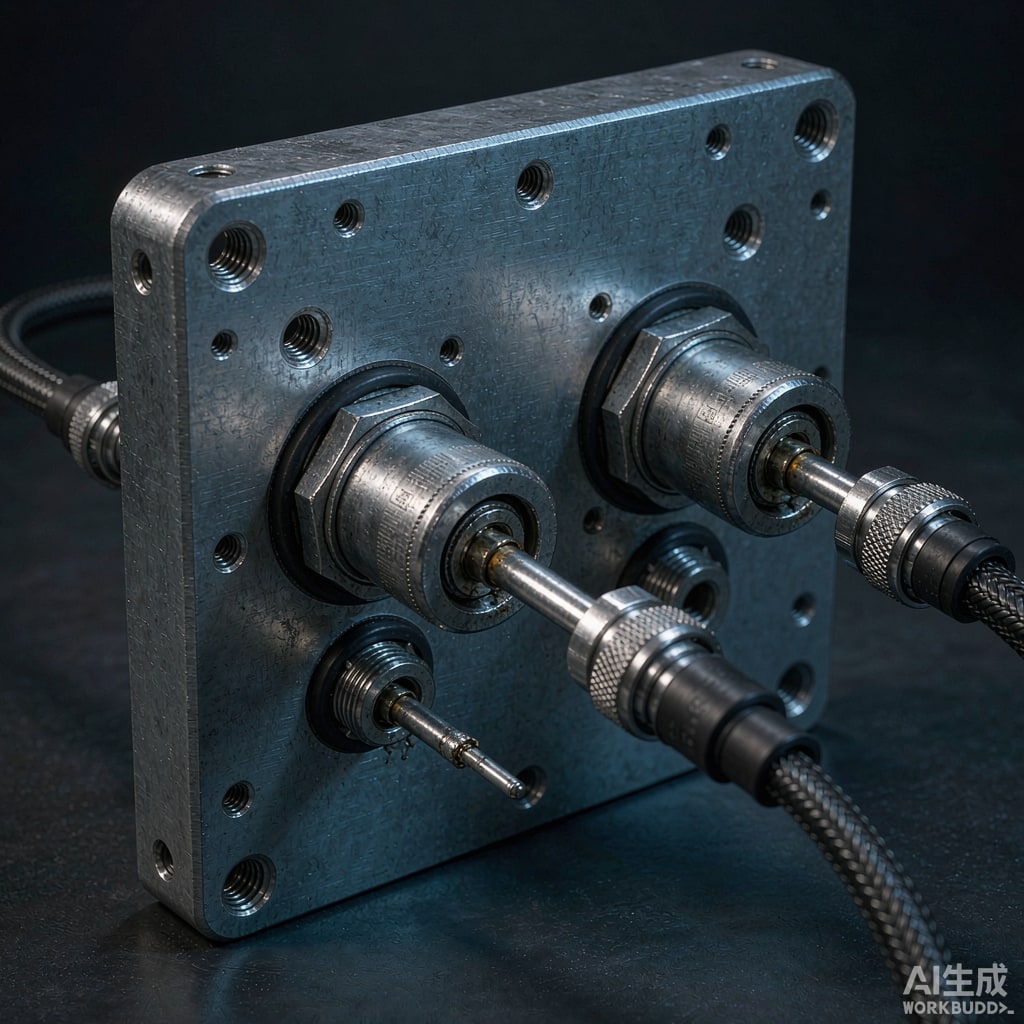
The Weakest Point in Your Shield Is the Hole You Drilled
You can build a beautifully shielded enclosure with laser-tight seams and conductive gaskets, and lose 30 dB of its performance the moment a single unfiltered cable crosses the boundary. A cable entering a shielded box is an ante
a on both ends: it picks up or radiates common-mode current along its entire length, and its shield — terminated imperfectly — bridges the shielded volume to the noisy world outside. The standard fix is to treat the enclosure wall as a filter boundary: feedthrough filters and bulkhead capacitors placed exactly where each conductor penetrates the metal.
What a Feedthrough Filter Actually Is
A feedthrough capacitor is a three-terminal device: the signal conductor passes through the center, the capacitor’s dielectric wraps around it, and the outer electrode bonds directly to the bulkhead (the enclosure wall). This topology is its superpower. Because the ground co
ection is coaxial and 360 degrees, there is essentially no parasitic inductance in the shunt path — a feedthrough rated 1 nF behaves like 1 nF at 1 GHz, where a regular 0805 decoupling capacitor with via inductance delivers a fraction of its nominal capacitance. Insertion loss curves for quality feedthroughs stay flat and deep (often 40–60 dB) from low MHz to several GHz.
Add series elements and you get feedthrough filters: C (capacitor only), LC (one inductor), Pi (capacitor-inductor-capacitor), and T topologies. Pi filters give the steepest stop-band slope and are the default choice for power lines crossing shield boundaries. T filters behave better with high source impedance and are common on signal lines.
Selection Rules
Start from the signal, not the spec sheet. The filter’s capacitance sits directly on the line, so it must be small enough not to distort the signal. Practical ceilings: 100–470 pF for USB 2.0 and other fast differential lines (and often no bulkhead capacitor at all — use 360-degree shield termination instead), 1–10 nF for slow digital and RS-485 style signals, and 100 nF to 10 µF (ceramic feedthroughs in parallel arrays) for DC power. Check the rated current and DC resistance of the series inductor in LC and Pi types — power feedthroughs carrying several amps need low DCR to avoid dropping voltage, and inductors saturate; verify the rated current has margin above your worst-case load including inrush.
Voltage rating should exceed the bus by 2× at minimum, and for safety-relevant lines (mains input), use Y-rated feedthrough capacitors with the appropriate certification rather than general-purpose parts. Environmental ratings matter in tropical deployments: hermetically sealed glass-to-metal sealed feedthroughs resist the humidity-driven leakage current creep that eventually degrades epoxy-sealed types.
Mounting Is Half the Performance
The Bulkhead Must Be the Ground
A feedthrough only performs as well as its wall co
ection. Torque to specification, ensure the mounting hole finish is conductive (no anodize or paint in the contact a
ulus — mask before coating), and use EMI gaskets or conductive washers where the panel is not bare metal. One frequent failure: the enclosure is powder-coated, the filter is mounted through the coating, and the entire 50 dB insertion loss exists only on the datasheet.
Cable Side Discipline
The filtered side should face the clean interior; the noisy side faces the cable. Anything between the filter and the cable exit is an ante
a attached to your clean node — keep that pigtail as short as physically possible, ideally zero. If the cable is shielded, terminate its shield 360 degrees to the bulkhead at the same entry point (EMI backshells), so shield currents flow into the wall rather than around the filter. D-separated entry: group filtered entries away from unfiltered penetrations (like status LEDs or ante
a feedthroughs) to prevent re-coupling on the outside of the wall.
Common Failure Modes
Field failures in feedthrough installations cluster into four patterns. First, ground path detour: the filter body is bolted to a bracket that is bolted to the wall — the extra inductance wrecks high-frequency performance. Bolt directly to the wall. Second, flex cracking: rigid multilayer ceramic feedthroughs on panels that flex under thermal cycling or vibration crack silently; resilient mounting washers and strain-relieved cables reduce this. Third, corrosion at the interface: dissimilar metals (aluminum wall, steel washer, tin-plated body) with condensation create galvanic cells; use compatible platings and sealed hardware in marine or tropical environments. Fourth, re-coupling inside: filtered power conductors routed parallel to unfiltered signal wires inside the box re-inject noise; keep them separated or shielded internally.
Verifying the Installation
Two bench checks catch most errors. Surface transfer impedance-style testing: with the enclosure closed, inject a common-mode disturbance onto the cable outside and measure the noise appearing on an internal node — a spectrum analyzer and a near-field probe suffice for a comparative before/after. And a simple shielding effectiveness check: with the cable entries as the only penetrations, scan the outside of the wall with a probe while a known source runs inside. If emissions hug the cable exits, your filter or backshell termination needs work; if they hug a seam, go back to the gasket. Fix the wall first, then the cables — but never forget that in most real products, the cables were the problem all along.



