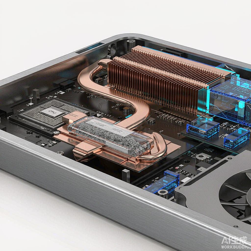
Thin electronics — fanless notebooks, edge AI boxes, 1U appliances — need to move 10–60 W of heat from an SoC to a remote fin stack through a chassis that is often less than 15 mm thick. Heat pipes are the standard answer, but almost every design requires flattening a round pipe to fit, and flattening is where thermal designs quietly lose capacity. Understanding the interaction between flattening, wick structure, and orientation prevents most of these surprises.
How a Heat Pipe Works, Briefly
A heat pipe is a sealed copper vessel holding a working fluid (usually water for electronics) and a capillary wick. At the hot end, liquid evaporates; vapor flows to the cold end and condenses; the wick pumps liquid back by capillary action. The cycle has hard limits: capillary limit (the wick ca
ot pump fast enough), boiling limit (the wick dries locally at high heat flux), and vapor limit (the vapor core chokes). Flattening stresses the first two.
Flattening: What You Lose and Why
Reduced Vapor Space
Flattening a 6 mm round pipe to 2 mm thickness crushes the vapor core, raising vapor velocity for the same power. Above roughly 15 m/s vapor velocity, pressure drop grows steeply and the pipe approaches its vapor limit earlier. As a rule of thumb, a standard 6 mm pipe rated 45 W horizontal may deliver only 25–30 W after flattening to 2 mm, depending on length.
Wick Compression
The sintered powder wick sits on the wall. Flattening compresses the wick against the flat wall, reducing its permeability — the capillary pump loses flow capacity. The opposite face’s wick also deforms. Good manufacturers control flattening so wick compression stays within limits; cheap pipes do not, which is why nominally identical pipes vary 20–30% in capacity between vendors.
Wall Contact Benefit
Flattening is not all loss: the flat wall gives a large contact area against the SoC and the fin stack, cutting contact thermal resistance versus a round pipe touching at a tangent line. For short pipes (under 100 mm) the contact gain can offset some capacity loss.
Sintered Wick Design and Selection
Sintered copper powder wicks dominate thin SMT applications because they work against gravity and support flattening. Key parameters:
- Wick thickness: 0.4–0.8 mm typical. Thicker wicks pump higher (better anti-gravity) but occupy vapor space. Thin 0.4 mm wicks favor horizontal, high-power runs.
- Powder size: 60–150 µm. Finer powder gives higher capillary head but lower permeability. Vendors tune the blend; ask for the test report rather than assuming.
- Composite wicks: Grooved walls plus sintered arteries give the best capacity in long horizontal pipes but cost more and tolerate flattening poorly. For flattened pipes, uniform sintered wick is the safer choice.
Orientation and Temperature Penalties
Heat pipe capacity is orientation-dependent because gravity helps or fights the wick. For a typical sintered-wick flattened pipe:
- Horizontal: 100% of rated capacity.
- Evaporator below condenser (gravity-assisted): 120–150%.
- Evaporator above condenser (anti-gravity): 50–70%, worse at elevated temperature.
Since most devices operate in multiple orientations, derate to the anti-gravity case for the specification, then verify at max ambient with the device in its worst orientation. Also note capacity drops as operating temperature moves away from the water’s optimal range; below 30°C and above 90°C, expect 10–20% reduction.
Integration Rules for Thin SMT Designs
- Keep bend radius above 3× pipe thickness. Flattened pipes crack at tight bends; if routing is needed, buy pre-formed pipes from the vendor’s standard tooling.
- Flat spots only where needed. Flattening only the contact zones and keeping the pipe round between them preserves most capacity. Specify “flatten at evaporator and condenser only” in drawings.
- Thermal interface: A 0.5–1.0 mm gap pad under the fin stack absorbs tolerance stack-up; a thin phase-change or grease layer at the SoC minimizes contact resistance.
- Check Qmax at real temperature. Vendor datasheets quote Qmax at 60°C operating temperature; run the operating point comparison, not the headline number.
- Solder or clip mounting: Soldered pipes transfer heat best but constrain rework; mechanical clips with pressure maintain serviceability for 20–40 W designs.
Validation Testing
Sample-test flattened pipes from production tooling, not prototypes. Measure case temperature at the SoC with thermocouples while sweeping power from 25% to 120% of design load in both orientations. A healthy design shows a smooth, moderate temperature rise; a drying wick shows a sudden temperature knee — back off 20% from that knee for the continuous rating. Add a thermal cycling check (−20°C to +70°C, 100 cycles) because repeated freezing degrades some sintered wicks by trapping non-condensable gas, which visibly shortens the effective evaporator.
Summary
Flattened heat pipes are reliable workhorses when their physics is respected: flattening costs vapor space and wick permeability, sintered wicks handle flattening best, orientation derating is real and must be specified, and contact-area gains only pay off with flat, clean mounting surfaces. Budget 60–70% of a round pipe’s rated capacity for a flattened equivalent, verify with samples from production tooling, and thin SMT thermal designs will hold their margins.



