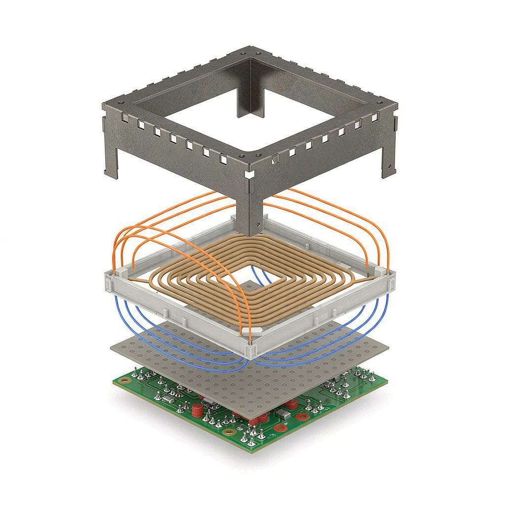
Wireless charging is an EMI engineer’s paradox: the product radiates power on purpose, and every regulator on the planet still demands that the radiated field stay inside tight spectral masks. A Qi pad, a medical implant charger, or a 3 kW industrial wireless power link all face the same triangle — couple energy efficiently, contain the magnetic field, and pass CISPR and FCC measurements. Shielding strategy sits at the center of that triangle.
Where the Emissions Actually Come From
The resonant coil itself is the intentional radiator; regulators manage it through field-strength limits and frequency bands rather than shielding. The unintentional emitters are the power electronics around it: the switching stage operating at 100 to 500 kilohertz with fast edges, the rectifier and communication demodulator on the receive side, and — critically — the ground loops that couple coil currents into signal grounds. Differential-mode current in the coil loop radiates predictably, but common-mode current on the transmit board’s ground and attached cables is usually what fails a CISPR 32 measurement at 30 to 200 megahertz.
Ferrite Sheets: The First Line
Beneath and around the coil, ferrite shielding sheets do double duty. They raise the coil’s effective inductance and Q by redirecting flux away from lossy metal backs (a charger with a bare metal case loses 20 to 40 percent efficiency to eddy currents), and they attenuate stray flux that would otherwise reach nearby electronics. Material selection follows the operating frequency: manganese-zinc ferrites in the 100 to 500 kilohertz band for Qi-class systems, with permeability around 600 to 1500 and low loss density; nickel-zinc ferrites for higher frequencies. Sheet thickness of 0.1 to 0.5 millimeters saturates quickly at high flux — for multi-watt systems, sintered ferrite plates or laminated amorphous ribbons outperform flexible composite sheets because composite sheets embed the ferrite powder in a polymer matrix that dilutes effective permeability.
Watch the interaction between ferrite and shield can: a grounded aluminum can placed directly over a coil behaves like a shorted transformer secondary. Keep the can several coil diameters away from the high-flux zone, or accept the efficiency hit and thermal load.
Shield Cans and Board Zoning
On the PCB itself, conventional board-level shielding still applies to the switching controller, driver ICs, and communication receiver. A soldered shield can over the receiver’s demodulation circuitry is often the difference between a working Qi interop certification and months of debugging foreign-object-detection false triggers, because the demodulator works with millivolt-level signals on a coil that sits millimeters from a 20-amp switching node.
Zoning rules for wireless power boards deserve explicit treatment in your layout guidelines. Separate the coil and resonant tank region from the DC-DC and control region with a ground fence of stitching vias at intervals below one-twentieth of the highest harmonic wavelength. Route all feedback and communication traces away from the coil’s backside flux path, even with ferrite present — ferrite attenuates, it does not eliminate. Keep single-point co
ections between power ground and signal ground, and place the common-mode choke on any cable leaving the board; a clip-on ferrite on the DC input line solves many 30 to 108 megahertz failures cheaply.
Foreign Object and Thermal Interactions
Two wireless-power-specific issues interact with shielding. Metal foreign objects on the pad concentrate flux and heat rapidly; both regulatory and safety standards require detection, typically by Q-factor monitoring, and your shielding scheme must not blind the Q measurement — an over-aggressive ferrite layer can damp the very signal the detector needs. Thermally, ferrite sheets have poor conductivity and act as insulating blankets between coil and case. Transmit pads ru
ing above 15 watts need either thermally conductive ferrite composites or deliberate thermal vias and spreaders routed around, not through, the flux path.
Pre-Compliance Workflow
Build the EMI budget early: near-field probe scans of the coil plane at 100 kilohertz and of the board plane at 10, 30, and 100 megahertz locate both flux leakage and common-mode hotspots before a chamber visit. A small shielded enclosure with filtered feedthroughs lets you A/B ferrite materials and can geometries on the bench in minutes. Regulatory field measurements for Qi-class devices concentrate between 9 kilohertz and 30 megahertz in most jurisdictions; design the compliance plan around CISPR 16 measurements plus the specific wireless power standards in your target markets, since field strength limits for intentional magnetic radiators differ substantially from ordinary digital-device limits.
Wireless charging EMI is won at the layout stage, not the filter stage. Coil geometry, ferrite selection, and ground zoning decided in the first two weeks of design save more certification time than any late-stage shielding hardware ever will.



