The Warpage Signature of Glass-Filled Resins
Switch a co
ector base or enclosure bracket from unfilled resin to a glass-filled pellet—PA66 GF30, PBT GF30, PP GF20—and the first molded parts almost always come out warped. Glass fibers do not shrink, but they orient with flow, and oriented fibers freeze the melt’s shrinkage in a directional pattern: roughly 0.1–0.3% in the flow direction versus 0.5–1.0% transverse, depending on resin. That two-to-four-fold difference in differential shrinkage is the root cause of warpage in glass-filled molding, and every practical fix attacks it through orientation, geometry, or process.
Where Orientation Comes From
Shear at the flow front
Fibers align with the flow direction in the surface skin, where shear is highest, and remain more random in the core. Fill patterns that sweep long, straight distances before the part fills produce strong skin orientation; fountain flow near gates and rib junctions adds local disorder. The warpage bow you see in a flat plate is the surface layers’ flow-direction shrinkage fighting the transverse core shrinkage.
Gate location and number
A single edge gate on a long flat part guarantees a bowed parabola. Moving the gate to the geometric center, or using multiple gates to shorten flow length, cuts differential orientation dramatically. The trade-off is weld lines—place them where a rib or non-critical surface can hide them, and vent and seal them properly since glass-filled weld lines are 20–40% weaker.
Design-Side Fixes
- Balance thickness: keep nominal wall within ±15% of nominal; heavy sections shrink late and drag thin regions out of plane.
- Use ribs and corrugations to stiffen, not massive sections: a 1.5 mm corrugated panel stays flatter than a 4 mm flat one because it resists the residual moment.
- Add corner radii and draft early: sharp inside corners concentrate transverse shrinkage and crack around glass.
- Consider a flatness allowance: for known-bow geometries, pre-cambering the mold 0.5–1.5 mm lets the part relax flat—cheaper than fighting physics with process.
Process-Side Fixes
Mold temperature
Hotter tool steel (PA66 GF30 at 80–100°C, PBT GF30 at 60–90°C) lets the skin layer relax more before freezing, reducing locked-in orientation. Underheated molds are the most common cause of excessive bow in glass-filled parts.
Injection speed and packing
Multi-stage speed—slow through the gate region, faster mid-fill—moderates skin shear. Packing pressure must be high enough to feed transverse shrinkage but not so high that it over-packs near the gate; profiling pack pressure downward over 3–6 seconds flattens the shrinkage gradient along the flow path.
Cooling symmetry
Asymmetric cooling (hot A-side, cold B-side) makes the part bow toward the cold side immediately on ejection. Match coolant circuit temperatures within 3–5°C and verify with molded-in thermocouples during DOE trials, not just surface readings.
Drying and Material Handling
Moisture amplifies warpage: hydrolyzed PA66 chains shorten and shrink unpredictably. Dry nylon and PBT pellets to below 0.05–0.1% moisture (4–6 h at 80–120°C, dew point −30°C or better) and keep hopper air dry through the run. Reground material with different fiber length distribution shifts shrinkage between batches—cap regrind at 20–25% and requalify shrinkage whenever the regrind ratio changes.
Verification Workflow
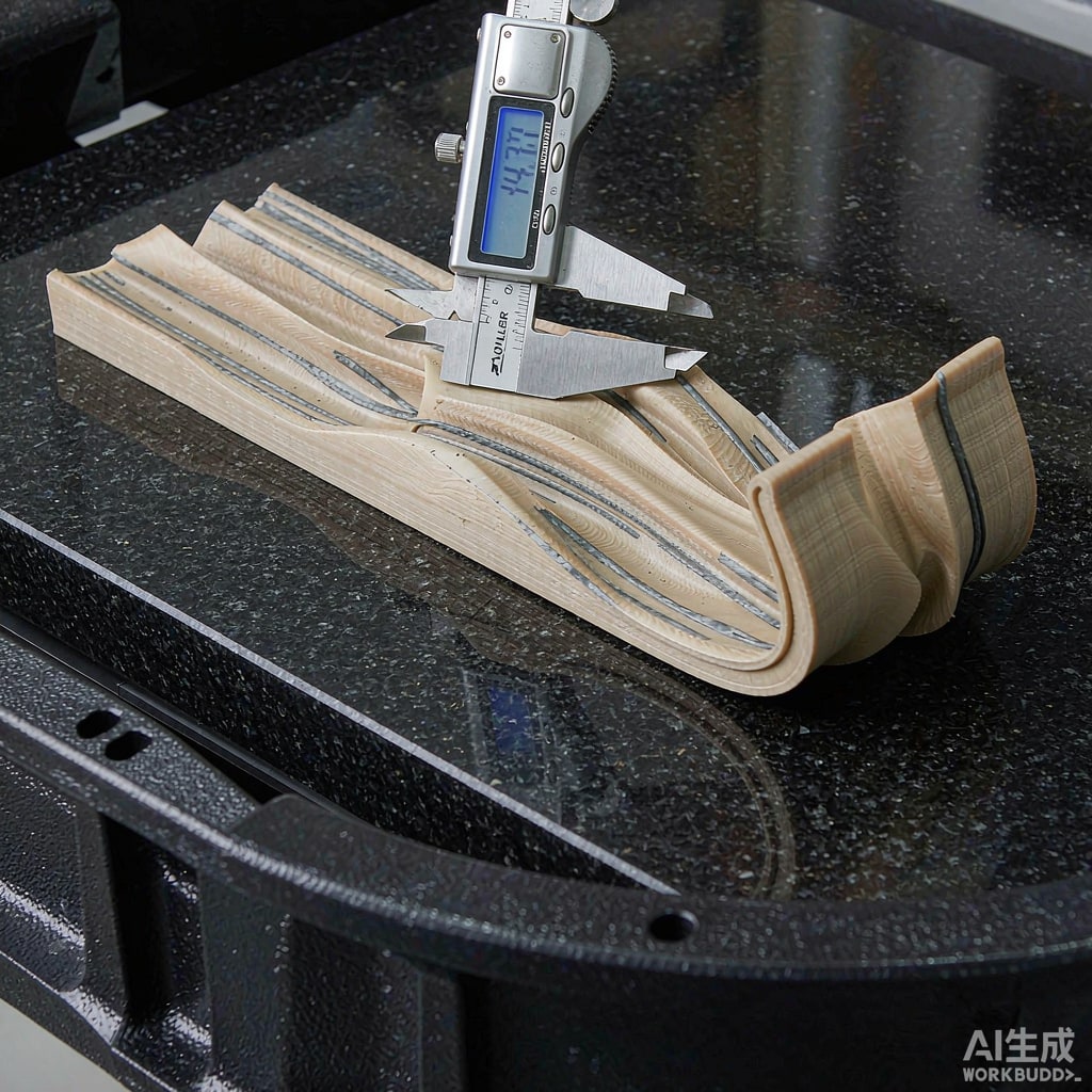
Measure flatness on a granite table at 30–60 minutes post-mold, since post-mold relaxation continues for 24 h; define both limits in the drawing. A short DOE over mold temperature, pack pressure, and holding time, with flatness as the response, typically finds a stable window within 16 runs. Warpage in glass-filled molding is never eliminated—only budgeted, measured, and controlled.



