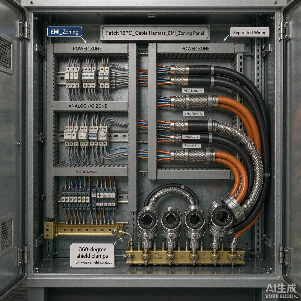
Modern industrial control panels combine variable frequency drives (VFDs), switching power supplies, relays and contactors, servo drives, and sensitive analog instrumentation — all inside a single steel cabinet. The most common cause of unexplained PLC resets, jittering analog readings, and intermittent communication faults is not software: it is cable harness routing that lets switching noise couple from power cables into signal wiring. This guide sets out practical segregation and zoning rules that prevent those problems at design time.
Understanding the Noise Sources
What generates EMI in a panel
VFD output cables are the worst offenders. Fast-switching IGBTs (2–16 kHz carrier plus nanosecond edges) put hundreds of volts of dV/dt and significant common-mode current onto motor cables, which then radiate and couple capacitively into anything nearby. Contactors and relays generate broadband transients on coil interruption. Switching power supplies contribute conducted noise back onto the DC distribution. Each of these travels by four coupling paths: common impedance on shared conductors, capacitive coupling (worst with high dV/dt), inductive coupling (worst with high di/dt loops), and direct radiation from long unterminated runs.
Zoning the Cabinet
Divide the panel into four zones and keep wiring in its own zone wherever possible:
- Zone 1 — Power: incoming mains, main breakers, drive input power.
- Zone 2 — Drive output and dirty power: VFD-to-motor cables, DC bus wiring, switched 24 V feeding inductive loads.
- Zone 3 — Control signals: digital I/O, relay contacts to PLC inputs, communication buses.
- Zone 4 — Sensitive analog: thermocouples, RTDs, strain gauges, pH and flow transmitters, 4–20 mA loops.
Physically separate the zones vertically or laterally inside the cabinet: power at the bottom (heavier components, and gravity keeps drips and debris away from electronics), drive outputs routed in their own cha
el, and sensitive analog at the top, furthest from the drives and the door hinges where grounding is weakest. Never run VFD motor cables in the same wiring duct as analog signal pairs — a 10 cm parallel run over 2 m is enough to inject measurable noise into a thermocouple loop.
Separation distances
Common guidance from panel-building practice: maintain at least 200 mm between VFD output cables and unshielded analog signal wiring; 100 mm between drive outputs and general digital control wiring; 50 mm minimum between 230/400 V AC power and low-voltage DC wiring to satisfy basic insulation coordination. Where crossings are unavoidable, cross at 90° and keep the parallel overlap as short as possible. Inside ducts, use dividers — most slotted wiring ducts accept internal partitions precisely for this purpose.
Shielding and Grounding Practice
Motor and power cables
Use shielded motor cables rated for drive duty, with the shield terminated 360° at both ends — at the drive’s designated shield clamp and at the motor terminal box. Pigtail shield co
ections of even 10 cm measurably raise the impedance and defeat the shield at switching frequencies. Symmetric shielded cables (with a concentric shield covering three symmetrical conductors) reduce bearing currents and radiated emission compared with random-lay cables.
Signal cables
Shield analog pairs with twisted-pair shielded cable; ground the shield at one end for low-frequency analog loops (to avoid ground-loop hum) or both ends where the environment is dominated by high-frequency drive noise and the panel has a solid equipotential ground grid. In a well-bonded cabinet with all grounds referenced to one point, both-end grounding of analog shields is usually the better choice in drive-heavy panels. Digital buses (PROFINET, EtherCAT, Modbus RS-485) ship with specified shielded cables — follow the fieldbus standard’s grounding instructions and never route them in the same duct as motor cables.
Equipotential bonding
All segregation rules assume the cabinet has a low-impedance ground system: bare bonding conductors between the backplate, door, and cabinet frame, painted contact areas scraped or use of serrated washers, and drive PE terminals co
ected directly to the backplate bus rather than daisy-chained. Common-impedance coupling — drive return currents sharing a PE path with signal references — is invisible on a drawing but shows up as noise exactly where shields are grounded.
Practical Checklist
- Zone the cabinet: power bottom, drive outputs isolated, analog top.
- 200 mm drive-output-to-analog separation; 90° crossings where unavoidable.
- Use duct dividers; never mix motor and signal wiring in one cha
el.
- 360° shield clamps at both cable ends for motor cables; follow the drive manual’s cable spec.
- Twisted shielded pairs for analog; decide one-end vs two-end shield grounding by the ground grid quality.
- Bond door and backplate with braid or dedicated bonding straps.
- Keep a 50 mm clearance between 230/400 V wiring and SELV signal wiring.
Conclusion
Cable segregation is the cheapest EMI control available — it costs engineering attention at layout time instead of shielded everything, filters, and weeks of commissioning debugging later. Cabinets built with clear zoning, real separation distances, and disciplined shield grounding routinely pass EMC tests on the first attempt, while their improvising counterparts burn days chasing noise that a rerouted harness would have eliminated.



