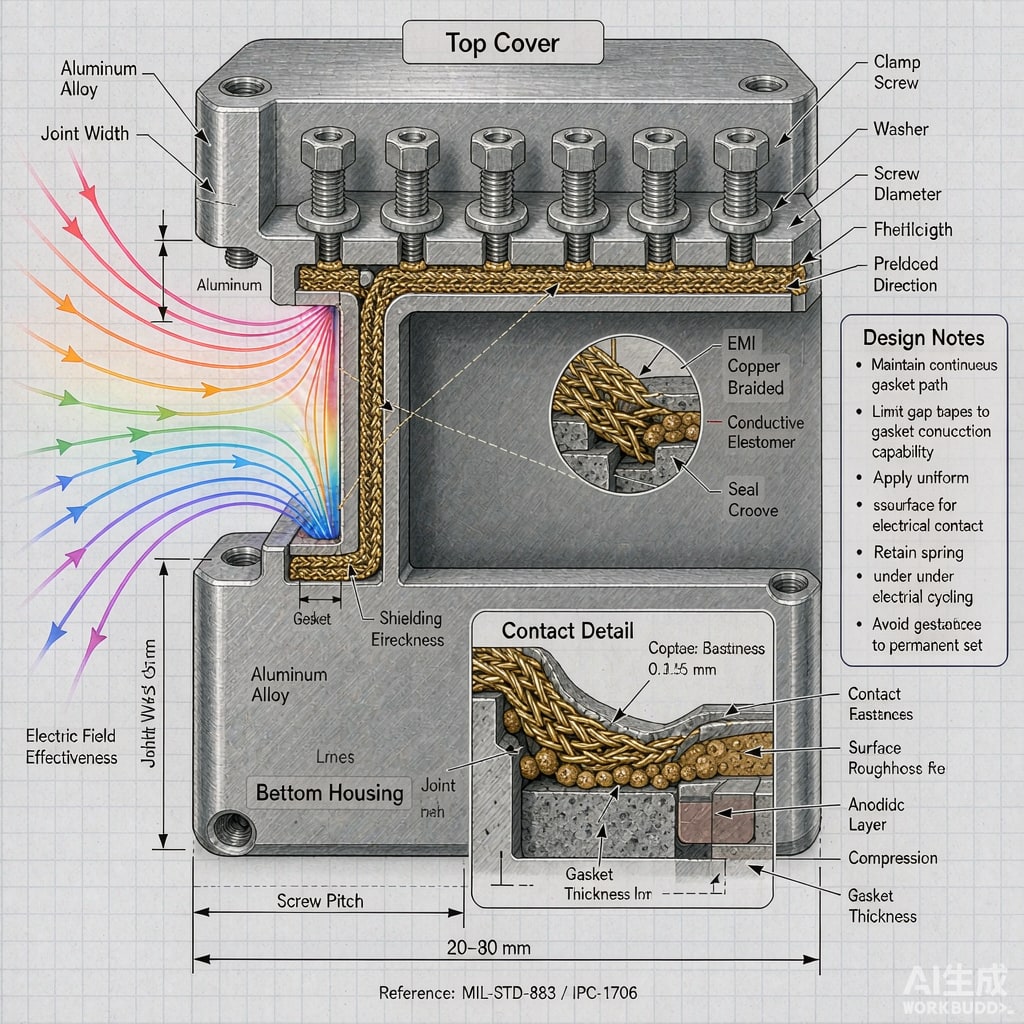
No practical shielding enclosure is made from a single piece of metal. Covers, doors, panels, and co
ectors all create seams, and seams are where electromagnetic energy leaks out or gets in. A seam that looks mechanically tight can still be transparent to radio frequency fields if the contact impedance is too high or the gap is too long. Designing seams for EMI therefore requires attention to screw spacing, flange surface finish, and the continuity of electrical contact.
Why Seams Leak
An enclosure seam behaves like a slot ante
a. When the seam length is comparable to a quarter-wavelength at the frequency of interest, it becomes an efficient radiator. At 1 GHz, the free-space wavelength is 300 mm; a seam longer than roughly 75 mm can leak. At 10 GHz, the threshold drops to 7.5 mm. The leakage is driven not only by physical gap width but by the electrical impedance across the joint. Paint, anodize, oxide, and corrosion all raise contact impedance and let fields pass even when the metal pieces appear to touch.
Screw Spacing Rules
The classic rule of thumb is to space fasteners so that the maximum seam length between them is less than λ/20 at the highest frequency of concern. In practice, this often means screw pitch of 20–50 mm for consumer electronics, and as tight as 10–15 mm for high-frequency RF enclosures. A more conservative approach ties spacing to the required shielding effectiveness: every halving of seam length can improve SE by 6 dB or more at frequencies dominated by seam leakage.
Screws must also create reliable pressure. A fastener that is loose, countersunk through paint, or installed in an insulating washer does not short the joint. Use thread-forming screws in metal bosses, star washers that bite through finish, or conductive PEM nuts where the enclosure is painted. Torque consistency matters; undertorqued screws leave gaps, and overtorqued screws can strip threads or distort flanges.
Surface Finish and Contact Impedance
The best seam starts with bare, conductive metal at the joint. Practices that reduce contact impedance include:
- Masking flanges before painting or powder coating so metal remains exposed
- Using conductive conversion coatings such as chromate or trivalent passivate on aluminum
- Avoiding hard anodize on mating surfaces; anodize is an insulator
- Specifying a surface roughness that breaks through oxide films without creating air gaps
For enclosures that must survive outdoor or marine environments, bare aluminum will oxidize and raise impedance. In these cases, a conductive gasket between flanges maintains a stable low-impedance path despite surface aging.
Combining Seams and Gaskets
When screw spacing alone ca
ot provide enough shielding, a conductive gasket extends the effective contact. Mesh-over-elastomer, finger stock, and conductive fabric-over-foam are common choices. The gasket must be compressed into its specified window — too little and contact is spotty; too much and the material takes a set. Fastener spacing then sets how uniformly the gasket is compressed. For large covers, use enough screws so deflection between fasteners keeps compression within ±10% of target.
Measuring Seam Performance
Shielding effectiveness is measured per IEEE 299, MIL-STD-285, or IEC 61587-3. During development, near-field probing along seams quickly identifies hot spots. A seam that passes at low frequencies may fail at harmonics from a switching regulator or 5G clock. Test both the best-case freshly assembled unit and a sample that has undergone temperature cycling and corrosion aging to confirm that seam performance holds through the product life.



