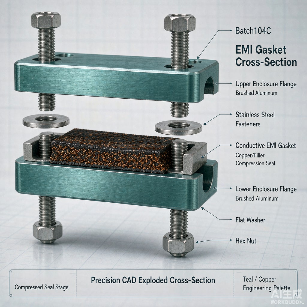
An EMI gasket only delivers its datasheet shielding effectiveness inside a specific compression window. Compress it too little and contact resistance stays high; compress it too much and the gasket takes a permanent set, losing force and eventually leaking both RF and moisture. Getting compression, force, and fastener design right is the difference between an enclosure that passes EMC testing and one that drifts out of compliance within a year.
Compression Fundamentals: Percent and Window
Gasket compression is specified as a percentage of original height. Typical target ranges by gasket family:
- Conductive elastomers (silicone or fluorosilicone filled with silver-aluminum, silver-copper, or nickel-graphite): 15–30% compression, optimum around 20–25%
- Mesh-over-elastomer and all-metal mesh (monel, tin-plated copper-clad steel): 25–40%, limited by mesh crush
- Finger stock / beryllium copper fingers: 15–50% of free height, with force rising roughly linearly
- Conductive fabric-over-foam: 25–50%, used heavily in telecom shield cans and doors
The datasheet compression range exists because force-deflection curves are steep. A conductive elastomer gasket compressed to 10% instead of 20% may deliver half the contact force; compressed to 35% instead of 25%, it may cross into compression set. Design the flange gap so nominal compression lands mid-range, leaving tolerance on both sides.
Flange Pressure Requirements
Shielding requires the gasket to conform to flange surface irregularities. Recommended contact pressures are typically 0.35–0.7 MPa for conductive elastomers — enough to displace surface oxide and fill micro-roughness. Below roughly 0.15 MPa, transfer impedance across the joint rises sharply, especially at higher frequencies where small gaps in contact dominate leakage.
Compute the required closing force as gasket contact area × target pressure, then add gasket spring rate effects: F = A × P + (K × Δh), where K is the gasket’s force-per-deflection constant. For a large door with a 3-meter gasket perimeter on 6 mm-wide elastomer, this lands in the range of kilonewtons — the reason big shielded-room doors use latch-assisted compression mechanisms rather than pure clamp screws.
Fastener Spacing: Keeping Compression Uniform
The Stiffness Problem
Flanges are not infinitely rigid. Between fasteners, the flange deflects away from the gasket, and compression falls toward mid-span. For a simply supported flange of thickness t and modulus E, mid-span gap grows with the cube of the unsupported span. Practical rules:
- For 2 mm aluminum flanges, fastener pitch of 50–75 mm keeps compression variation under ±10%
- For 3 mm steel or thick castings, 100–125 mm pitch is usually adequate
- Place a fastener within 10–15 mm of every gasket corner and at both ends of every gasket segment — corners are where compression goes to zero first
If fastener count is constrained (service doors, access panels), add a stiffening rib along the flange or switch to a lower-force gasket profile — a hollow or fi
ed conductive elastomer extrusion provides the same shielding at half the closing force.
Compression Set and Lifecycle Loss
Compression set — the permanent deformation retained after long dwell — is the silent killer of gasketed enclosures. Silicone conductive elastomers held at 25% compression and 85°C typically take a set of 10–20% of their compressed height over the first months, meaning the stored force decays even though the flange never moves. Countermeasures:
- Design to the middle of the compression range, never the top
- For products seeing elevated temperature (outdoor telecom cabinets, automotive electronics), specify low-set formulations and derate the closing force estimate by 20–30%
- Avoid over-torque: a torque-controlled spec matters more than a strength spec for gasket flanges; use calibrated torque or spring washers
- Verify with a force-film (pressure-mapping film) check on the first article — uniform print across the full gasket footprint, no light bands mid-span
Verifying Shielding With Compression Data
Shielding effectiveness datasheets are measured at optimum compression. When validating a design, measure transfer impedance or shielding across the compression range (per IEC 62153-4-3 or ASTM D4935 as applicable), including the minimum compression your tolerance stack can produce. A design that only meets spec at perfect compression is not a passing design. Combined with proper fastener spacing and a compression budget that tolerates aging, the gasket will hold its shielding performance through thermal cycling, door cycles, and years in the field.



