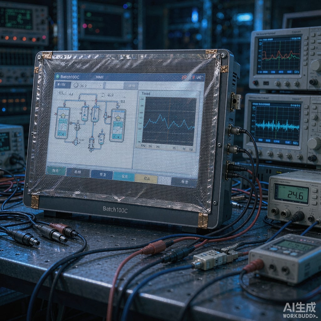
Industrial HMIs, medical monitors, kiosks, and military displays all share one unsolvable-looking problem: the glass or acrylic window is a hole in an otherwise shielded enclosure. Radio-frequency noise leaks out through it, and external interference leaks in. Transparent EMI shielding solves it — but each technology trades optical quality against shielding effectiveness differently. Here is how to choose.
The Four Practical Technologies
1. ITO (Indium Tin Oxide) coated glass or film
A transparent conducting oxide sputtered onto glass or polyester. Sheet resistance runs 10–100 Ω/sq for displays (lower resistance = better shielding). Optical transmission reaches 85–90 percent on glass, but shielding effectiveness is modest: roughly 20–30 dB at 1 GHz for a well-grounded 10 Ω/sq coating, falling quickly above a few GHz as the coating becomes capacitive. ITO is brittle on glass, and the indium content makes it the most expensive option per square meter at low resistance.
2. Woven copper mesh laminated between glass layers
Fine copper wire (12–50 µm diameter) woven into a 100–200 mesh grid, blackened to reduce visibility, laminated between two glass or acrylic sheets. This delivers the best shielding: 50–80 dB from 100 kHz through 10+ GHz, because it behaves as a real Faraday conductor, not a resistive film. Transmission is 60–75 percent, and under bright conditions a faint moiré or screen-door pattern is visible. Moiré with the underlying pixel grid is the classic failure mode — spec the mesh pitch against the display resolution, or rotate the mesh 7–15 degrees to break the beat pattern.
3. Blackened stainless steel micromesh
Same principle as woven copper, using stainless for corrosion resistance. Slightly worse conductivity and shielding (45–70 dB), slightly better long-term appearance in humid or coastal environments. Popular for outdoor kiosks and marine equipment.
4. Conductive film lamination (transparent conductive polyester)
Metallized or nanowire-coated PET films laminated to the window. A middle path: 60–80 percent transmission, 25–40 dB shielding, low cost, easy retrofit. Durability is the weak point — scratching and delamination over years of cleaning cycles.
Side-by-Side Comparison
| Option | Transmission | SE @ 1 GHz | SE @ 10 GHz | Visibility impact | Relative cost |
|---|---|---|---|---|---|
| ITO glass (10 Ω/sq) | 85–90% | ~25 dB | < 15 dB | None visible | High |
| Cu woven mesh | 60–75% | 60–80 dB | 40–60 dB | Slight texture/moiré | Medium-high |
| SS micromesh | 60–72% | 45–70 dB | 35–55 dB | Slight texture | Medium |
| Conductive film | 60–80% | 25–40 dB | 15–25 dB | Minimal | Low |
Grounding: Where Most Installations Fail
A shielded window without a low-impedance perimeter termination shields nothing. The conductive layer must bond to the enclosure shield along all four edges:
- Conductive gasket compression: clamp the mesh edge under a conductive EMI gasket in a milled frame cha
el — the gold standard for 60+ dB systems.
- Conductive tape or foil frame: acceptable up to roughly 30 dB, degrades over thermal cycling.
- Spring finger edging: good for doors and removable panels; keep finger pitch tight (≤ 25 mm) above 1 GHz.
Treat the window termination like a co
ector flange, not an afterthought. A 3 dB-per-octave degradation above the frequency set by the bond spacing is typical when edges are only spot-bonded.
Matching Technology to Application
- Medical and test instruments (mild emissions, excellent optics): ITO — invisible, and 25 dB is enough for most Class B compliance work.
- Industrial HMI in a noisy plant: stainless micromesh — durability and 50+ dB against VFD and switch-mode noise.
- Military/avionics and TEMPEST-class requirements: laminated copper mesh with gasketed frame termination.
- Cost-sensitive kiosks and vending: conductive film with conductive-tape framing.
Design Checklist
- Specify transmission at the actual display luminance you will run; a 70 percent mesh window needs a brighter backlight — check thermal budget in sunlight-readable designs.
- Check moiré: request a sample of the actual mesh over your actual display before committing.
- Plan the perimeter termination geometry in the enclosure CAD model, not on the shop floor.
- Remember optical bonding can fill the air gap behind the mesh, reducing internal reflections and improving contrast by 10–15 percent.
Conclusion
Transparent EMI shielding is a trade-off triangle of optical clarity, shielding effectiveness, and cost. ITO wins optics, woven copper wins shielding, and film wins budget. Pick by required attenuation and viewing conditions, then invest engineering effort where most shielded windows actually fail — the perimeter bond.



