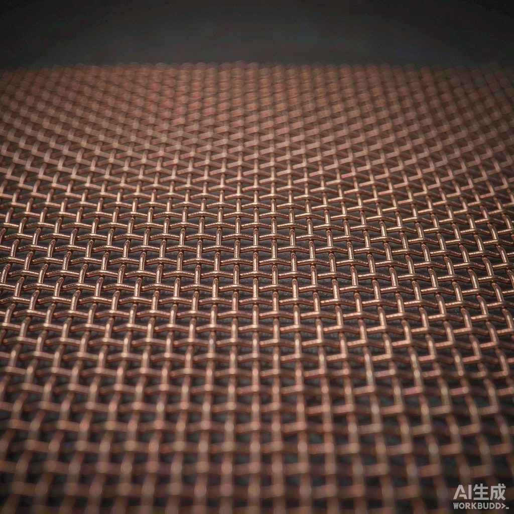
The Role of Conductive Mesh Screens in EMI Shielding
Conductive mesh screens are among the most versatile and cost-effective solutions for electromagnetic interference (EMI) shielding in electronic enclosures, ventilation panels, and optical windows. Unlike solid metal sheets, which block all electromagnetic energy but also airflow and visibility, conductive mesh screens provide a tunable compromise between shielding performance and physical transparency. Understanding the underlying aperture theory is essential for designing mesh screens that deliver adequate EMI shielding effectiveness across the frequency bands of interest.
Aperture Theory and the Waveguide-Below-Cutoff Principle
The shielding effectiveness of a conductive mesh is governed by the interaction between the electromagnetic wave and the periodic apertures formed by the mesh wires. When the aperture dimension (mesh opening) is small compared to the wavelength of the incident radiation, the aperture behaves as a waveguide below cutoff, attenuating the transmitted field exponentially. This is the same principle that applies to honeycomb vents and other perforated shielding structures.
For a square aperture of side length a, the cutoff wavelength is λc = 2a. The shielding effectiveness (SE) in dB for a single aperture of depth t is approximately:
SE ≈ 32 × (t/a) dB (for electric fields, when λ >> a)
In practice, mesh screens consist of many apertures in parallel, and the overall shielding effectiveness is reduced by approximately 20 log₁₀(√N) for N apertures, where N is the number of apertures per unit area. This explains why finer meshes (smaller a, higher N) generally provide better shielding, all else being equal.
Key Mesh Parameters and Their Impact
Mesh Count and Wire Diameter
Mesh count, expressed as the number of openings per linear inch, together with wire diameter, determines the optical transparency and shielding performance. Common configurations include:
- 100 mesh (100 × 100 openings per inch): Wire diameter ~0.11 mm, opening ~0.144 mm. Provides >60 dB shielding below 1 GHz, with ~40% optical transmission.
- 200 mesh: Wire diameter ~0.053 mm, opening ~0.074 mm. Provides >80 dB below 1 GHz, with ~25% optical transmission.
- 80 mesh: Wire diameter ~0.14 mm, opening ~0.178 mm. Provides ~50 dB below 1 GHz, with ~50% optical transmission.
Material Selection
The conductivity and permeability of the mesh material directly influence shielding effectiveness:
- Copper: Excellent conductivity, good for electric field shielding across all frequencies. Often chosen for cost-effectiveness.
- Nickel: Moderate conductivity but higher corrosion resistance. Suitable for marine or outdoor applications.
- Monel (Ni-Cu alloy): Superior corrosion resistance with acceptable conductivity. Common in aerospace and naval applications.
- Mu-metal or Co-NETIC: High permeability materials essential for low-frequency magnetic field shielding (<1 kHz). Must be used in combination with conductive meshes for broadband protection.
Design Rules for Optimal Shielding Performance
1. Aperture Size vs. Wavelength
As a general rule, the maximum aperture dimension should be less than λ/20 at the highest frequency of concern. For a 6 GHz 5G NR band, this translates to a maximum aperture of 2.5 mm. For microwave applications up to 18 GHz, a 200 mesh copper screen is typically required.
2. Mesh-to-Frame Bonding
The mesh must make continuous electrical contact with the conductive frame or enclosure around its entire perimeter. Gaps or loose contacts create slot ante
as that can actually enhance EMI transmission rather than suppress it. Conductive gaskets, soldered joints, or compression contacts are recommended.
3. Multi-Layer Configurations
For applications requiring both high shielding and high optical transmission, two or more mesh layers can be stacked with an insulating spacer. The offset between layers disrupts the periodicity and reduces the effective aperture size. A double-layer 100 mesh configuration can approach the shielding of a single 200 mesh while maintaining higher overall transparency.
4. Angle of Incidence
Shielding effectiveness degrades as the angle of incidence deviates from normal. For oblique incidence, the effective aperture dimension increases as a/cos(θ), reducing shielding by approximately 20 log₁₀(cos(θ)) dB. In applications with known off-axis radiation sources, orient the mesh normal to the dominant threat direction or specify a higher mesh count to compensate.
Measurement and Validation
Shielding effectiveness is typically measured using the MIL-STD-285 or IEEE 299 test methods, which involve illuminating the mesh sample with a known field and measuring the transmitted field strength. For mesh screens, special attention must be paid to:
- Edge sealing to prevent leakage around the test sample
- Illumination uniformity across the mesh area
- Frequency sweep coverage from the lowest threat frequency to at least 10× the highest
Applications in Modern Electronics
Conductive mesh screens find application in CRT and LCD display EMI shielding, microwave oven door windows, medical equipment viewing ports, and secure communication facility windows (TEMPEST). In the SMT and electronics manufacturing context, mesh screens are also used in shielded test enclosures, anechoic chamber windows, and cleanroom pass-through air filtration with EMI protection.
Conclusion
By applying aperture theory and following established design rules, engineers can specify conductive mesh screens that deliver the required EMI shielding effectiveness while preserving the necessary airflow, optical clarity, or other functional requirements. The key is to match mesh count, material, and mounting method to the specific electromagnetic threat environment and frequency spectrum of the application.



