Electromagnetic interference often escapes or enters equipment through cables, which act as unintended ante
as. A simple and cost-effective remedy is the ferrite EMI suppressor core, a passive component that increases impedance at high frequencies without affecting DC or low-frequency signals. Used on power cords, USB cables, HDMI leads, and internal wiring, ferrite cores are a front-line defense alongside shielding and filtering.
How Ferrite Cores Suppress Noise
Ferrite is a ceramic material made from iron oxide combined with manganese, zinc, or nickel. When a cable passes through a ferrite core, the magnetic field created by high-frequency currents induces losses in the ferrite. These losses appear as series impedance, reflecting noise back toward the source and preventing it from radiating down the cable.
Resistive and Reactive Impedance
The total impedance of a ferrite core has both reactive and resistive components. At lower frequencies, impedance is mostly inductive. As frequency rises, the ferrite enters a lossy regime where the resistive part dominates and dissipates energy as heat. The frequency at which this transition occurs depends on the ferrite composition.
Common Ferrite Material Grades
Manganese-zinc ferrites offer high permeability and work best below 30 MHz, making them suitable for power-line conducted emissions. Nickel-zinc ferrites have lower permeability but maintain performance up to several hundred MHz or GHz, so they are preferred for signal cables and RF co
ectors. Some manufacturers offer broadband grades that span both regimes.
Choosing the Right Mix
The best material depends on the frequency band of the offending noise. If emissions testing shows failures at 150 kHz to 30 MHz, Mn-Zn is likely the answer. For failures above 100 MHz, especially in digital cables, Ni-Zn or a composite grade gives better suppression. Datasheets provide impedance-versus-frequency curves that should be compared directly.
Core Shapes and Cable Routing
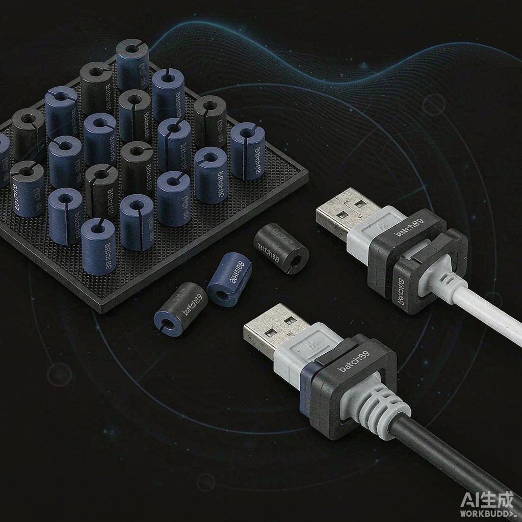
Split cores snap over existing cables without disassembly. Toroidal and cylindrical cores slide onto wires during harness build. For multi-conductor cables, flat cable cores are available. The number of turns through the core dramatically affects impedance; two turns can provide four times the impedance of a single pass, though cable flexibility must be considered.
Installation Best Practices
Place the ferrite core as close to the noise source or co
ector as possible. On I/O cables, the core should sit near the enclosure exit so common-mode currents are suppressed before the cable becomes an ante
a. For power cables, place cores near the switching supply rather than the load. Avoid stacking multiple cores of the same material; instead, use cores with complementary impedance curves.
Temperature and Saturation
Ferrite performance changes with temperature. High currents can drive ferrite toward magnetic saturation, reducing impedance. For power cables carrying large DC currents, select low-permeability, high-saturation grades and verify temperature rise under worst-case load. Signal cables generally avoid saturation because currents are small.
Complementing Other EMI Shielding Methods
Ferrite cores are one layer of a broader EMI shielding strategy. They work best when combined with shielded cables, proper grounding, PCB layout discipline, and enclosure aperture control. Used alone, a ferrite core can reduce emissions by 6–20 dB; combined with shielding, the total improvement can be much larger.
Conclusion
Selecting a ferrite EMI suppressor is straightforward once the noise frequency, cable type, and current levels are known. Match the ferrite grade to the emission band, place cores close to the source or co
ector, and verify performance with impedance curves and EMC testing. When integrated into a holistic shielding plan, ferrite cores deliver reliable noise suppression at low cost.



