The Challenge of Cooling Shielded Enclosures
Server racks, telecom cabinets, medical equipment housings, and military shelters must often satisfy stringent electromagnetic interference (EMI) emission and immunity standards. At the same time, the power electronics inside these enclosures generate significant heat that must be removed to prevent thermal throttling and premature component failure. Solid metal panels provide excellent electromagnetic shielding but block airflow, while ordinary ventilation openings compromise shielding effectiveness. EMI shielding honeycomb vent panels solve this dilemma by allowing air to pass while attenuating electromagnetic waves across a broad frequency range.
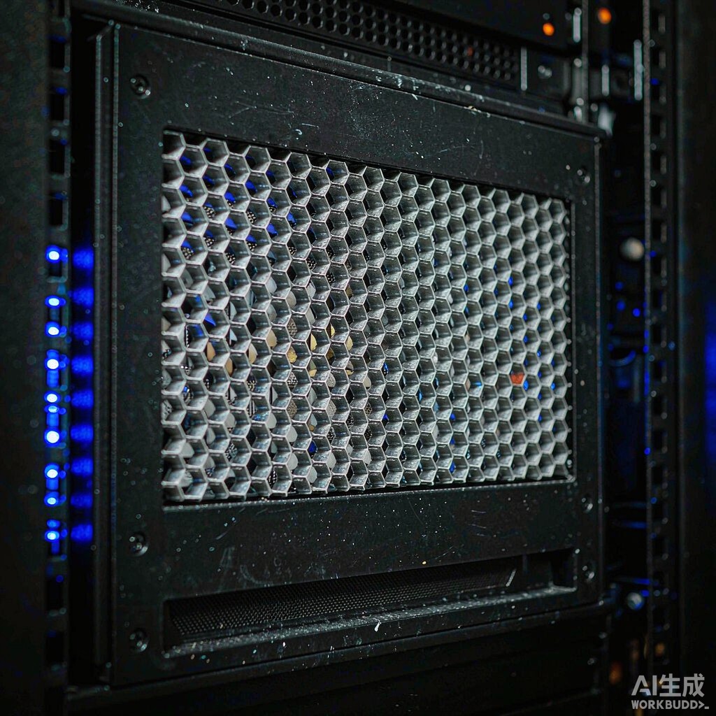
Honeycomb vent panels are constructed from a matrix of small, precisely formed hexagonal or square cells bonded between metal frames. The geometry of each cell acts as a waveguide below cutoff, presenting a high impedance to electromagnetic energy while offering low aerodynamic resistance to cooling air. This article explains the operating principles, material options, performance specifications, and installation practices for EMI shielding honeycomb vent panels used in server rack enclosures.
Waveguide Below Cutoff Operation
The shielding mechanism of a honeycomb vent relies on the waveguide-below-cutoff effect. Each cell in the honeycomb functions as a short section of rectangular or circular waveguide. When the wavelength of an incident electromagnetic wave is significantly larger than the critical cutoff wavelength determined by the cell’s cross-sectional dimensions, the waveguide presents an attenuation that increases exponentially with cell depth. For practical honeycomb vents, cell widths are typically 3.2 mm to 6.4 mm, with depths ranging from 6.4 mm to 25 mm or more.
This geometry provides high attenuation for frequencies up to several gigahertz while maintaining open areas of 85–95%, allowing efficient airflow. A typical aluminum honeycomb vent with 3.2 mm cells and 12.7 mm depth can deliver shielding effectiveness exceeding 100 dB at 1 GHz when properly installed with conductive gaskets and continuous frame bonding. The same panel will exhibit pressure drops comparable to an ordinary perforated steel vent of similar free area, making it an attractive solution for thermally dense server racks.
Material Options and Surface Finishes
Honeycomb vent panels are most commonly manufactured from aluminum, steel, or brass. Aluminum offers the best combination of low weight, corrosion resistance, and cost, making it the dominant choice for commercial data center and telecommunications enclosures. Steel provides higher mechanical strength and magnetic shielding at low frequencies, which is advantageous for industrial control cabinets and military applications. Brass or nickel-plated steel may be specified when galvanic compatibility with the enclosure frame or marine corrosion resistance is a concern.
Surface finishes include bare aluminum with chromate conversion coating, tin plating, nickel plating, and conductive painting. The choice depends on the operating environment and the EMI gasket material used. Tin and nickel plating improve solderability and corrosion resistance while maintaining electrical continuity. For high-humidity or salt-fog environments, such as coastal telecom huts or shipboard server racks, stainless steel or nickel-plated aluminum honeycomb is often specified.
Frame, Gasket, and Mounting Design
The frame surrounding the honeycomb core is critical to overall shielding performance. A continuous, low-impedance electrical bond must be established between the vent frame and the enclosure aperture. Most designs use a conductive EMI gasket—oriented wire mesh, conductive elastomer, or finger stock—compressed between the frame and the chassis. The gasket material must be selected for environmental compatibility; for example, conductive silicone gaskets tolerate outdoor exposure better than knitted wire mesh in some climates.
Mounting screws should be spaced closely enough to prevent frame bowing and gasket relaxation. A common rule of thumb is one fastener every 75–100 mm along the frame perimeter. Screws should be made of corrosion-resistant material and used with star washers to bite through any paint or oxide layer on the enclosure. For removable panels, captive fasteners or quarter-turn latches with conductive plating help maintain shielding integrity across repeated service cycles.
Cutoff Frequency and Shielding Effectiveness
The cutoff frequency of a honeycomb cell is inversely proportional to its largest transverse dimension. Smaller cells block higher frequencies but reduce airflow and increase pressure drop. For server rack enclosures that must comply with CISPR 32 or FCC Class A emission limits up to 1 GHz, 3.2 mm or 4.8 mm cells are usually adequate. For applications involving 5G millimeter-wave, radar, or high-speed digital signals with significant energy above 6 GHz, smaller cells or deeper honeycomb stacks may be required.
Shielding effectiveness is typically measured according to IEEE 299, MIL-STD-285, or ASTM D4935, depending on the industry. Designers should request test data from the vent panel supplier that matches the frequency range and test method required by the end application. It is important to remember that shielding effectiveness is a system property: even an excellent honeycomb panel will fail if installed with poor frame bonding, missing gaskets, or oversized mounting holes.
Conclusion
EMI shielding honeycomb vent panels are an essential component in server rack and enclosure design, reconciling the conflicting demands of electromagnetic compliance and thermal management. By selecting the appropriate cell size, material, surface finish, and mounting hardware, engineers can achieve shielding effectiveness well above 100 dB while preserving the airflow needed to cool modern power-dense electronics. As data centers, edge computing, and 5G infrastructure continue to push power densities higher, honeycomb vent panels will remain a trusted solution for shielded ventilation.



