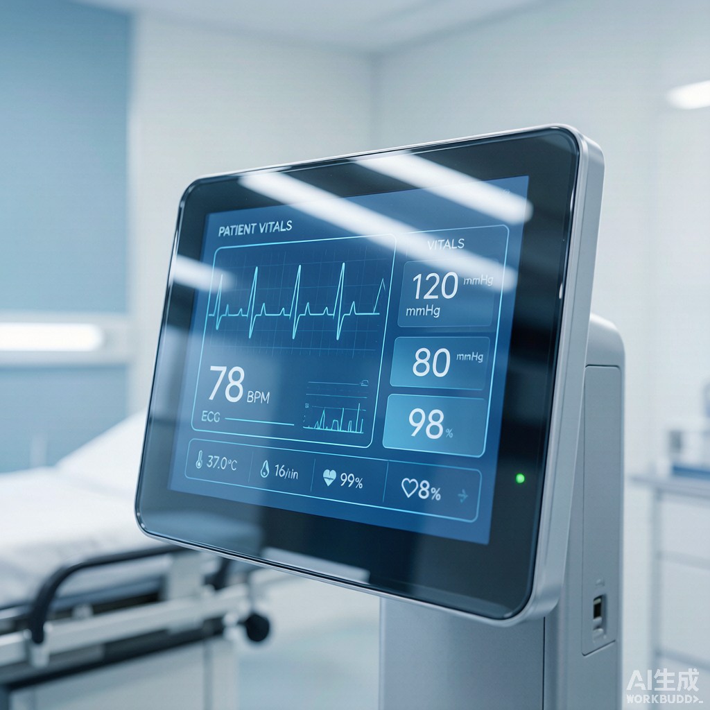
Medical device touch panel displays—patient monitors, infusion pumps, ultrasound consoles, ventilators, and surgical robot HMIs—require both optical transparency for user interaction and electromagnetic interference (EMI) shielding to prevent internal digital electronics from radiating through the display window into sensitive adjacent equipment, and to prevent external RF sources (RFID readers, electrosurgical units, MRI gradient fields) from coupling into the display electronics. Indium tin oxide (ITO) sputter-coated glass or polycarbonate windows provide 60-85% visible-light transmittance combined with 1-100 Ω/sq sheet resistance, achieving 25-50 dB EMI shielding effectiveness at 1 MHz to 18 GHz. This article examines the ITO sputtering process, sheet resistance vs optical transmittance trade-off, ASTM D1003 haze and clarity metrics, ISO 13485 medical device regulatory requirements, capacitive touch sensor integration, and 7H surface hardness qualification for hospital-grade displays that must withstand alcohol wipe disinfection 50+ times per day.
Why ITO for Transparent EMI Shielding
Material Properties Comparison
Several transparent conductive materials compete for EMI shielding window applications, but ITO remains the dominant choice for medical and industrial touch panels due to its unique balance of optical, electrical, and mechanical properties:
| Material | Sheet Resistance (Ω/sq) | Transmittance @ 550nm | Hardness | Cost Index | EMI SE @ 1 GHz |
|---|---|---|---|---|---|
| ITO (90% In₂O₃ / 10% SnO₂) | 1-100 | 75-90% | 6-7H pencil | 1.0× (baseline) | 25-50 dB |
| FTO (fluorine-doped tin oxide) | 5-20 | 75-82% | 7-8H | 0.7-0.8× | 20-35 dB |
| Silver nanowire (AgNW) mesh | 10-50 | 85-92% | 2-3H (soft) | 0.6-0.9× | 20-45 dB |
| Copper mesh (photolithography) | 0.1-1 | 75-85% (Moiré-dependent) | 6-7H | 1.5-2.5× | 40-70 dB |
| Conductive polymer (PEDOT:PSS) | 50-500 | 80-88% | 2-3H | 0.4-0.6× | 15-30 dB |
| Carbon nanotube (CNT) film | 30-200 | 80-90% | 3-4H | 2-4× (small-batch) | 20-40 dB |
ITO delivers the best combination of high transmittance (75-90%), tunable low sheet resistance (1-100 Ω/sq), and excellent surface hardness (6-7H pencil) for touch panel durability. Silver nanowire offers higher transmittance at comparable sheet resistance but suffers from poor abrasion resistance and oxidation-induced long-term stability issues that have limited medical device adoption. Copper mesh provides the best EMI SE but introduces Moire pattern artifacts in high-resolution displays and adds 50-150% cost premium.
Where ITO is Indispensable
ITO sputtering is the only transparent conductive coating that has achieved FDA 510(k) clearance history for Class II and Class III medical device displays, with major OEMs (Philips, GE Healthcare, Siemens Healthineers, Mindray, Dräger) specifying ITO on capacitive touch panels in their product lines. The 30+ year manufacturing history, supply chain maturity (3 major ITO sputtering equipment vendors: Applied Materials, ULVAC, Von Arde
e), and well-characterized aging behavior in hospital environments make ITO the de facto standard for medical device transparent EMI shielding.
Sputtering Process & Coating Stack
Magnetron Sputter Deposition
ITO thin films are deposited by DC or RF magnetron sputtering from a 90/10 In₂O₃/SnO₂ ceramic target (or 90/10 In/Sn metallic target in reactive mode) onto glass or polyethylene terephthalate (PET) substrate. Process parameters that govern film quality and sheet resistance:
- Substrate temperature: 250-350°C for soda-lime or aluminosilicate glass (high-temp process), or 80-150°C for PET or polycarbonate (low-temp process). High-temp produces crystalline ITO with 1-5 × 10⁻⁴ Ω·cm bulk resistivity; low-temp produces amorphous ITO with 3-10 × 10⁻⁴ Ω·cm resistivity.
- Sputter power: 1-5 kW per target, with deposition rate 10-30 nm/min.
- Argon + oxygen partial pressure: Ar 0.3-0.8 Pa, O₂ 0.005-0.02 Pa. Oxygen stoichiometry controls film transparency and conductivity; under-stoichiometric films are darker (reduced) and more conductive, over-stoichiometric films are lighter but more resistive.
- Film thickness: 20-200 nm typical for touch panel and EMI shielding applications. Thicker films (100-200 nm) achieve lower sheet resistance (1-5 Ω/sq) but reduce transmittance and increase cost.
Multi-Layer Anti-Reflection Stack
For medical displays requiring 85%+ transmittance and minimal color shift, the ITO layer is integrated into an anti-reflection (AR) optical stack. A common 4-layer AR+ITO configuration deposited on the rear side of cover glass:
- Cover glass (0.5-1.1 mm aluminosilicate): 6-7H hardness, anti-glare (AG) or anti-reflection (AR) top surface
- ITO layer (50-150 nm): sputtered at 250-300°C
- SiO₂ or Nb₂O₅ index-matching layer (60-100 nm): optical impedance matching to enhance transmittance
- Organic polymer OCA (optically clear adhesive, 50-200 µm): bonds ITO-glass to LCD/OLED panel
This 4-layer stack achieves 86-92% transmittance, 0.5-1.5% haze, EMI SE 30-50 dB at 1 GHz, and survives 5,000,000 finger touches (10 mm capacitive stylus, 100g force) without electrical or optical degradation.
Sheet Resistance vs Transmittance Trade-Off
Optical-Electrical Coupling
ITO sheet resistance and visible-light transmittance are inversely related because both are governed by film thickness and free carrier density. Higher carrier density (heavily doped ITO) reduces sheet resistance but increases free-carrier absorption in the visible spectrum, particularly at longer wavelengths (red), giving the film a yellow-green tint. This trade-off is fundamental to all transparent conductive oxides:
| Sheet Resistance (Ω/sq) | Film Thickness (nm) | Transmittance @ 550nm | EMI SE @ 1 GHz | Application |
|---|---|---|---|---|
| 1-2 | 300-500 | 70-78% | 50-65 dB | Aerospace/military displays (SE priority) |
| 5-10 | 150-250 | 78-85% | 40-50 dB | Hospital monitors (balance) |
| 20-50 | 50-120 | 85-90% | 25-35 dB | Patient infotainment (clarity priority) |
| 100+ | 20-40 | 88-92% | 10-20 dB | Touch-only, no SE requirement |
Application-Driven Selection
For patient monitors and infusion pumps where 30-40 dB SE at 1-6 GHz suffices (radiated emission compliance per IEC 60601-1-2), 5-10 Ω/sq ITO at 150-200 nm thickness is the industry sweet spot. For operating room surgical displays and ICU ventilators where 40-50 dB SE is required (proximity to electrosurgical units up to 500 kHz and MRI 64-128 MHz fundamental), 1-5 Ω/sq ITO at 300-400 nm is needed, accepting 75-80% transmittance. For patient infotainment touch screens with no SE priority, 20-50 Ω/sq at 50-100 nm is the cost-optimized choice.
EMI Shielding Effectiveness Verification
Test Methods ASTM D4935 vs IEEE 299
Two primary test standards govern ITO window SE measurement:
- ASTM D4935 (far-field, coaxial holder): 30 MHz to 1.5 GHz, flat sample 76 mm diameter. Quick QC test, suitable for production sampling. Reports SE in dB with reference to NIST-traceable calibration load.
- IEEE 299 / IEEE 1128 (reverberation chamber or TEM cell): 1-18 GHz, sample size 0.5-1.0 m² representative of actual installation. Used for design qualification and re-verification after tooling changes.
Typical SE Spectrum for ITO
A 10 Ω/sq ITO film on 1.1 mm aluminosilicate glass (150 nm thickness) measured per ASTM D4935 shows frequency-dependent SE:
| Frequency | SE (dB) | Coupling Mechanism |
|---|---|---|
| 30 MHz | 25-30 | Magnetic near-field |
| 100 MHz | 32-38 | Transition to plane wave |
| 500 MHz | 38-45 | Plane wave, absorption dominant |
| 1 GHz | 42-48 | Plane wave, absorption + reflection |
| 3 GHz | 40-45 | Plane wave, reflection |
| 6 GHz | 38-43 | Plane wave, reflection + slot leakage |
| 10 GHz | 35-40 | Slot/aperture leakage from bezel gaps |
| 18 GHz | 30-35 | Slot/aperture leakage dominant |
The 10 GHz and 18 GHz roll-off is dominated by the bezel-to-glass interface gap, not the ITO itself. To improve high-frequency SE, the ITO coating must be extended under the bezel with a continuous silver-loaded epoxy or conductive foam gasket at the perimeter, ensuring that the conductive path is unbroken around the display circumference. This is a critical design detail often overlooked in production drawings.
Medical Device Regulatory & Reliability
ISO 13485 & FDA 510(k) Documentation
Medical device displays using ITO-coated windows must include the following in the FDA 510(k) submission or CE Technical File per EU MDR 2017/745:
- Biocompatibility per ISO 10993-1: ITO is a stable inorganic oxide and is considered non-hazardous, but cytotoxicity (ISO 10993-5), sensitization (ISO 10993-10), and irritation tests are typically run on coated parts to qualify the cover lens-to-skin contact scenario (e.g., wearable patient monitors).
- Cleaning chemical resistance per ISO 10993-13 / ASTM F483: 70% isopropyl alcohol, 0.5% sodium hypochlorite (bleach), quaternary ammonium compounds (quats), and accelerated hydrogen peroxide (AHP) wipe resistance for 50+ wipe cycles. ITO on aluminosilicate glass passes all four with <2% transmittance change.
- EMI compliance per IEC 60601-1-2 (4th edition): radiated emissions CISPR 11 Group 1 Class A or Class B limits, immunity per IEC 61000-4-3 (radiated RF) and IEC 61000-4-6 (conducted RF). ITO window must be qualified as part of the device-level test in the actual housing.
- MOPP / MOOP per IEC 60601-1: Means of Patient Protection and Means of Operator Protection. ITO coating itself is not a MOPP, but the cover lens must not bridge isolation distances. ITO edge termination typically maintains 4 mm minimum creepage and 2.5 mm clearance to any patient-contact conductive trace.
Touch Sensor Integration
ITO serves dual purpose in most medical touch panel designs: (1) EMI shielding layer, and (2) projected capacitive (PCAP) touch sensor electrodes. The same ITO film is patterned by photolithography into a 5-10 mm diamond or rectangular electrode matrix, with X and Y electrodes on opposite sides of the cover glass (or stacked via separate ITO layers with insulator between). Mutual capacitance change between adjacent electrodes is detected by a touch controller IC (e.g., Microchip ATMXT336UD, NXP PCA8885, Ilitek ILI2511), reporting 80-120 Hz touch sampling rate. The ITO sheet resistance for touch is typically 50-200 Ω/sq (higher than for pure SE), but combined with the lower SE requirement (15-25 dB at 1 GHz suffices for most Class B radiated emission tests), the dual-purpose approach works well.
Surface Hardness & Durability
Pencil Hardness Test ASTM D3363
ITO on aluminosilicate glass reaches 6-7H pencil hardness (Wolff-Wilborn test, 1 kg load, 45° angle), and with chemically strengthened glass (ion exchange in KNO₃ salt bath at 420-480°C, producing 30-50 µm compressive stress layer with 600-900 MPa surface compression), reaches 8-9H. The ITO layer itself adds no significant scratch resistance beyond the substrate, but it is durable enough to withstand 50,000+ Taber abrasion cycles (CS-10F wheel, 500g load) per ASTM D4060 with <5% transmittance loss.
Hospital Disinfection Compatibility
Medical displays are routinely wiped with disinfectants 5-50 times per day. The ITO coating must survive this without cracking, delaminating, or losing conductivity. Compatible disinfectant chemistries include:
- 70% isopropyl alcohol (IPA): 50,000+ wipe cycles, no ITO degradation
- 0.5-1.0% sodium hypochlorite (NaOCl, bleach): 5,000-10,000 wipe cycles, no ITO degradation
- Quaternary ammonium compounds (benzalkonium chloride): 50,000+ wipe cycles
- Accelerated hydrogen peroxide (AHP, 0.5-1.5% H₂O₂): 50,000+ wipe cycles
- Peracetic acid (PAA, 0.2%): 1,000-2,000 wipe cycles, marginal ITO compatibility
- Glutaraldehyde (2%): 1,000+ wipe cycles, marginal ITO compatibility
The cover lens should be specified as chemically strengthened aluminosilicate (Corning Gorilla Glass 3 or equivalent) for hospitals using bleach or PAA-based disinfectants.
Conclusion
ITO sputter-coated transparent EMI shielding windows provide 75-90% visible transmittance and 1-100 Ω/sq sheet resistance, achieving 25-50 dB SE at 1 MHz to 18 GHz for medical device touch panel displays. The 5-10 Ω/sq ITO at 150-200 nm thickness represents the optimal balance for hospital monitors and infusion pumps requiring 30-40 dB SE plus projected capacitive touch sensing, and is compatible with 70% IPA, bleach, and quat disinfectants used in hospital cleaning protocols. The bezel-to-glass interface is the critical design detail for high-frequency SE, requiring silver-loaded epoxy or conductive foam gaskets to maintain 30-40 dB SE at 10-18 GHz. ISO 13485 documentation, IEC 60601-1-2 EMI testing, and ISO 10993 biocompatibility qualification are required for FDA 510(k) and CE MDR submission of medical devices using ITO-shielded touch panels, and supply chain maturity (3 major sputtering equipment vendors, 10+ coating service suppliers globally) makes ITO the de facto standard for transparent EMI shielding in hospital-grade electronics.



