5G IoT and industrial IoT gateways operating in the sub-6 GHz FR1 band (700 MHz to 6 GHz) require enclosure-level EMI shielding effectiveness (SE) of 60-80 dB across the full band to prevent desensitization of receiver front-ends and to contain radiation from high-speed digital sub-systems. The cover-to-base seam, I/O co
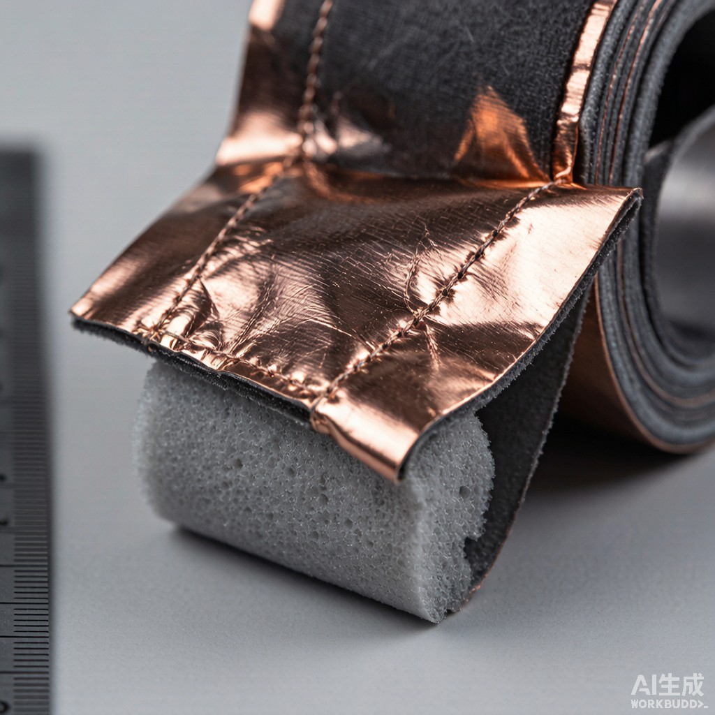
ector aperture, and LED/display windows are the dominant leakage paths that degrade overall enclosure SE even when individual shielding components are correctly specified. Conductive fabric over foam gaskets — consisting of a resilient polyurethane foam core wrapped in metallized textile fabric — provide the combination of low contact force (<1 N/cm compression), wide operational frequency range, and corrosion-resistant galvanic compatibility required for these seams. This article examines the engineering principles, shielding performance, and design considerations for conductive fabric over foam gaskets in 5G IoT enclosures.
Conductive Fabric Construction
Substrate Fabric Options
The fabric substrate carries the conductive coating and provides mechanical durability for repeated compression cycles:
- Polyester (PET) fabric: Most common substrate, tensile strength 25-45 N/cm warp / 15-25 N/cm weft, allowing fabrication in narrow widths down to 1.5 mm. Copper-nickel (Cu/Ni) metallization with 0.5-1.5 µm nickel over 1-3 µm copper provides bulk conductivity 0.005-0.02 Ω/sq.
- Polyamide (nylon) fabric: Superior flex endurance (1,000,000+ compression cycles vs 200,000 for polyester), preferred for high-cyclic applications such as frequently serviced test equipment covers. Higher moisture absorption (4-6% vs <1% for PET) requires sealed edge treatment in tropical climate.
- Non-woven fabric (carbon-coated): Lower cost option for commodity IoT devices where shielding target is 40-50 dB; bulk conductivity 1-5 Ω/sq and tensile strength 10-20 N/cm.
Conductive Coating System
Surface resistivity of the metallized fabric determines DC contact resistance and low-frequency shielding performance. The shielding performance ladder for common metallizations:
| Coating | Surface Resistivity (Ω/sq) | SE at 1 GHz (dB) | Galvanic Compatibility | Cost Index |
|---|---|---|---|---|
| Cu/Ni (ASTM B736) | 0.005-0.02 | 75-85 | Aluminum, stainless, zinc | 1.0x |
| Ni (pure) | 0.05-0.2 | 60-75 | All metals | 1.2x |
| Cu (bare) | 0.01-0.05 | 70-80 | Steel only; oxidizes in humid | 0.7x |
| Ag (silver) | 0.001-0.005 | 85-95 | Best, but silver migration risk | 3.5x |
| SnCu (tin-copper) | 0.02-0.08 | 65-75 | Aluminum risk; tin whisker | 0.9x |
Foam Core Specification
The resilient foam core determines compression-deflection characteristics and creep resistance:
- Polyurethane (PU) foam density 25-45 kg/m³: Standard EMI gasket foam, compression set <10% after 1,000 cycles at 25% deflection, recovery time <2 seconds.
- Poron XRD (high-recovery PU): Closed-cell PU with compression set <5% after 10,000 cycles, premium choice for high-end 5G base station equipment where service life exceeds 10 years.
- EPDM (closed-cell rubber): Better thermal tolerance (-40°C to +120°C vs -20°C to +80°C for PU) and IP67 sealing integration, suitable for outdoor 5G CPE enclosures with environmental sealing requirement.
Compression Deflection and Galvanic Compatibility
Compression-Deflection Curve Design
The compression-deflection curve defines the closure force required for the gasket to achieve metal-to-metal contact between the conductive fabric and the enclosure flange. The recommended operating range is 25-50% deflection of nominal gasket height:
| Gasket Height (mm) | Closure Deflection (mm) | Typical Force (N/cm) | SE at 25% (dB) | SE at 50% (dB) |
|---|---|---|---|---|
| 1.0 | 0.25-0.50 | 0.8-2.5 | 55-65 | 70-78 |
| 1.5 | 0.38-0.75 | 0.6-2.0 | 60-70 | 75-85 |
| 2.0 | 0.50-1.00 | 0.4-1.5 | 65-75 | 80-90 |
| 3.0 | 0.75-1.50 | 0.3-1.2 | 70-80 | 85-95 |
Galvanic Compatibility
Galvanic corrosion at the gasket-to-enclosure contact interface drives long-term shielding degradation. The compatibility matrix for typical 5G IoT enclosure materials:
- Aluminum alloy 6063/6061 enclosure + Cu/Ni fabric: Compatible. Cu/Ni over Aluminum galvanic potential difference <0.15 V produces negligible corrosion at 25-35°C/80-95% RH tropical conditions. Recommended pairing for cost-effective mid-tier 5G CPE.
- Stainless steel 304/316 enclosure + Cu/Ni fabric: Excellent compatibility. Stainless passivation layer minimizes galvanic drive; recommended for medical and food-grade 5G IoT devices.
- Zinc-plated steel enclosure + Cu/Ni fabric: Acceptable, but requires conductive steel flange geometry with full gasket compression. Avoid for outdoor deployment where zinc corrosion exposes underlying steel.
- Magnesium alloy enclosure + Cu/Ni fabric: Use tin-copper metallized fabric only; copper against magnesium produces 0.9 V driving potential causing rapid galvanic attack.
Adhesive System for Tropical Humidity
Pressure-Sensitive Adhesive Backing
Conductive fabric gaskets commonly include pressure-sensitive adhesive (PSA) backing for assembly onto the enclosure flange. Tropical climate operation (30-35°C / 75-95% RH) demands high-performance PSA chemistry:
- 3M 9485PC (acrylic adhesive): High-temperature (180°C short-term) and high-humidity adhesion retention. 180° peel strength 12-18 N/cm on aluminum substrate, retention 75-85% after 1,000 hours at 85°C/85% RH.
- 3M VHB 4611 (acrylic foam tape): Viscoelastic foam tape, ideal for vibration-tolerant 5G mobile CPE. 50% higher initial tack than standard acrylic PSA, but requires 72-hour dwell time for full bond strength.
- Silicone PSA (Dow 7657): Wide temperature range (-55°C to +260°C), suitable for outdoor 5G base station enclosures in tropical climates with direct sun exposure.
- Rubber-based PSA: Lowest cost but degrades above 80°C and shows adhesion loss above 70% RH; not recommended for tropical deployment.
Conductive Adhesive Layer
For EMI-critical applications, the PSA layer incorporates conductive filler (silver-coated copper particles or nickel particles) at 5-15 wt% loading. This creates a parallel conductive path through the adhesive bond line in case of partial adhesive delamination, ensuring continuous shielding continuity. Conductive PSA adds 25-40% cost premium but eliminates the catastrophic shielding failure mode of standard non-conductive PSA delamination in tropical cycling environments.
Seam Geometry Design
Gasket Groove and Closure Tolerance
Effective gasket deployment requires control of the mating flange groove and closure tolerances. For an enclosure cover with 1.5 mm gasket height:
- Groove width: Gasket width + 0.2 to + 0.5 mm tolerance for assembly clearance
- Groove depth: Gasket height + 0.3 to + 0.6 mm to permit 20-40% compression at closure
- Surface roughness: Ra <1.6 µm on mating flange to maintain electrical continuity; surface conversion coating (chromate on Al, passivation on SS) protects against in-storage corrosion prior to assembly
- Flatness: <0.1 mm across 100 mm span to avoid gap-region leakage even at full gasket compression
I/O Aperture and Co
ector Feedthrough
At I/O co
ector apertures where a gasket must surround multiple pins or maintain continuity around a circular co
ector cutout, the gasket is fabricated as a die-cut shape with continuous conductive fabric. Typical I/O gasket patterns achieve SE of 65-75 dB from 700 MHz to 6 GHz with aperture leakage contributing less than 5 dB degradation versus solid enclosure SE. For D-Sub co
ector apertures specifically, continuous flange gasket geometry is preferred over segmented pieces to eliminate gap discontinuities at corner joints.
Testing and Validation
Shielding Effectiveness Measurement
Three primary test methods validate fabric-over-foam EMI gasket performance:
- IEEE 299 / MIL-STD-285 (far-field enclosure test): Full enclosure validation with transmit/receive ante
as 1-5 m from test sample. SE = 10 log (P_without / P_with). Validates end-to-end assembly performance but requires large anechoic environment.
- ASTM D4935 (coaxial transmission line, planar sample): Bench-scale test of flat gasket material with 50 Ω coaxial fixture, frequency range 30 MHz to 1.5 GHz (or up to 6 GHz with extended-range fixtures).
- Near-field probe sca
ing:
Localized probe sweep across enclosed PCB radiating trace to identify seam hot spots. Mobile probe technique allows 0.5-1 mm spatial resolution at 1-10 GHz.
Conclusion
Conductive fabric over foam EMI gaskets provide 60-90 dB shielding effectiveness across the full 5G FR1 sub-6 GHz band with low closure force (<1 N/cm) and corrosion-resistant galvanic compatibility suitable for tropical deployment. The optimal selection balances substrate fabric (PET or nylon), metallization (Cu/Ni for general use, Ag for premium), foam core (PU for general, Poron for high-cyclic, EPDM for environmental sealing), and PSA adhesive (acrylic or silicone for tropical humidity). For 5G IoT gateways serving Southeast Asian deployment, Cu/Ni over PET/PET-cored gasket with 3M 9485PC acrylic PSA delivers reliable 65-80 dB SE performance with 5-10 year service life. Design of groove geometry and closure tolerances to 25-40% gasket compression range ensures consistent shielding continuity across production variation.



