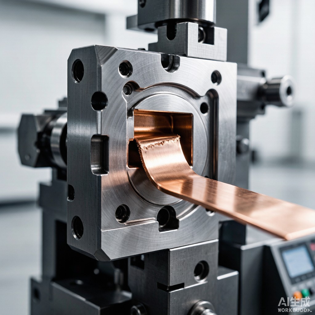
Precision progressive die stamping of SMT lead frames from copper strip stock at production rates of 600-1,200 strokes per minute creates an inherent edge burr condition that, if uncontrolled, propagates downstream into co
ector assembly defects including misaligned carrier strip engagement, plating thickness non-uniformity, and post-mold compound bleeding during IC encapsulation. Edge burr — the protrusion of material beyond the intended cut edge — forms through plastic deformation, shear fracture, and tear mechanism at the punch-die clearance interface, with burr height critically determined by the clearance ratio between punch and die. For high-reliability SMT co
ector lead frames operating in automotive, industrial, and aerospace applications, edge burr must be controlled below 25 µm on the contact edge and below 50 µm on the carrier strip edge to ensure both dimensional compliance and downstream processability.
Burr Formation Mechanism in Copper Strip Stamping
Tool Clearance and Burr Geometry
The clearance between punch and die determines the shear zone geometry, fracture initiation point, and resulting burr profile. For copper alloys commonly used in SMT lead frames (C11000 ETP, C19400 high-strength, C70250 CuNiSi, and C7521 brass), the optimal clearance-to-thickness ratio (c/t) falls in a narrow window:
| Alloy | Optimal c/t (%) | Clean Shear Range | Burr Height (µm) | Fracture Mode |
|---|---|---|---|---|
| C11000 (ETP) | 5-7 | 40-60% | 8-18 | Ductile rollover + shear |
| C19400 (HSLA) | 4-6 | 35-55% | 6-14 | Shear dominant |
| C70250 (CuNiSi) | 3-5 | 30-50% | 5-12 | Shear dominant |
| C7521 (CuZn) brass | 5-8 | 45-65% | 10-22 | Ductile rollover + shear |
| C52100 (CuSn phosphor) | 4-6 | 35-55% | 7-15 | Shear dominant |
Tool Wear Effect on Burr Growth
Punch and die wear progressively degrades cut quality throughout a tool life cycle. SKD11 tool steel (60-62 HRC) typically maintains burr height below 15 µm for 200,000-400,000 strokes; carbide tooling (WC-Co, K20 grade) extends the wear window to 1.5-3 million strokes before burr exceeds 25 µm. Hard chrome or DLC (diamond-like carbon) punch coatings reduce adhesive galling on copper-rich alloys, extending tool life by 2-3x in high-volume production. In humid Southeast Asian manufacturing environments where tool surface corrosion can accelerate galling, cryogenic treatment of tool steel (submersing in liquid nitrogen at -196°C for 20-40 hours) reduces retained austenite content and stabilizes tool hardness against thermal softening.
Inline Deburring Technology Selection
Mechanical Deburring Methods
Mechanical deburring processes the strip continuously between stamping and plating without chemical attack or thermal input:
- Rotary nylon brush deburring: Abrasive-impregnated nylon filament brushes (grit 320-600) ru
ing at 800-1,500 RPM opposite to strip travel direction remove burr peaks of 5-50 µm at strip speeds of 20-50 m/min. Brush pressure 2-8 N/cm² strip width controls depth-of-cut without removing base material.
- Vibratory bowl deburring (off-line batch): For prototype or low-volume production, vibratory finishing with ceramic or porcelain media removes burr from complex 3D formed parts that ca
ot be processed inline.
- Tumbling with abrasive media: For thicker lead frames (>0.3 mm), vibratory or centrifugal tumbling with triangular ceramic media removes heavy burr but compromises flatness for precision SMT components.
- Rotary brush with deburring disk: Combination of rotating brush and counter-rotating deburring disk achieves simultaneous top-and-bottom edge deburring in a single pass, suitable for strip widths 30-150 mm.
Thermal and Electrochemical Deburring
For applications where mechanical deburring risks damage to thin plated finishes or precision-stamped micro-features:
- Electrochemical deburring (ECD): Electrolytic dissolution of the burr tip in a neutral salt solution (NaNO₃ 15-25%) at 8-15 V DC. Removal rate 0.05-0.20 mm³/s with no mechanical force, ideal for ultralight burr below 30 µm where mechanical brushing would risk surface scratch.
- Thermal energy method (TEM): Hydrogen-oxygen combustion produces localized 3,000°C plasma that vaporizes the burr, but creates micro-cracks on copper alloys and is generally unsuitable for ductile copper or brass lead frames.
- Cryogenic deflashing: For molded-plastic-encapsulated lead frames, cryogenic deflashing with dry ice CO₂ pellets at -78°C followed by nylon brush tumble removes flash without chemical attack.
Inline Quality Verification
Optical and Laser Measurement
Inline burr height measurement directly influences SPC (statistical process control) loop closure:
- Laser triangulation profilometer: 1-5 µm resolution across strip width 20-150 mm at scan rates 200-1,000 profiles per second. Detects burr 5-500 µm with 0.5 µm repeatability.
- Confocal chromatic imaging: Sub-micron axial resolution suitable for precision measurement of burr profile shape, not just peak height.
- Machine vision (area-scan): 2D vision with backlight illumination detects burr direction and orientation; less accurate for absolute height but excellent for direction-based sorting.
SPC Control Limits and Cpk Targets
For SMT lead frame production, the burr height process capability target depends on application:
| Application | Burr Spec Max (µm) | USL (3σ) | Target Cpk | Sample Frequency |
|---|---|---|---|---|
| IC lead frame carrier strip | 50 | 65 | 1.33 | Every 5,000 strokes |
| Power co
ector contact |
25 | 35 | 1.50 | Every 1,500 strokes |
| Automotive lead frame (AEC-Q100) | 15 | 22 | 1.67 | Every 500 strokes |
| IC encapsulation post-mold | 75 | 90 | 1.25 | Every 10,000 strokes |
Plating and Solder Wettability Impact
Edge burr elevates plating thickness variation above the part edge, since burr peaks project into the electrolytic plating field lines and receive excess metal deposition. Tin plating on copper lead frame edges shows typical 1.5-2.5x thickness increase on burr peaks versus the flat surface; subsequent reflow creates tin-bead formation on burr tips causing co-planarity failures. For lead-free matte tin plating per IPC-4552, burr must be controlled below 25 µm for contact pitch 0.5-0.8 mm, and below 12 µm for ultra-fine pitch <0.4 mm.
Process Control Best Practices
Tool Wear Tracking
Implement cumulative-stroke counter on each progressive die with burr height SPC chart. Establish tool-change trigger at Cpk = 1.33 degradation. Pre-grind dies 3-4 times before major re-grinding to extend die life 4-6x total. Maintain tool steel hardness verification using portable Rockwell C hardness tester at every tool-return cycle.
Stamping Speed and Lubrication
Stamping speed directly affects burr formation via strain-rate sensitivity. Copper alloys show 10-15% burr height reduction when stroke rate decreases from 1,200 SPM to 600 SPM, but production economics typically favor high-speed operation with post-stamp deburring instead. Lubrication with synthetic metal-forming fluid (semi-synthetic emulsion 8-12% concentration) reduces punch friction and burr formation by 20-35% compared to dry stamping. For automotive AEC-Q100 lead frame production, laser-cut lead frame stock with pre-finished burr-free edges eliminates the stamping burr problem entirely but at 1.8-2.5x material cost versus standard slit-rolled strip stock.
Conclusion
Edge burr control in copper strip SMT lead frame stamping requires coordinated design of tool clearance (4-7% of stock thickness), tool material selection (carbide + DLC coating), inline mechanical deburring (rotary brush or ECD), and SPC-driven tool wear management. For high-reliability automotive and industrial co
ector applications, inline laser- or vision-based burr measurement with Cpk > 1.50 capability and aggressive deburring ahead of plating ensures downstream solder wettability and coplanarity compliance throughout the full tool life cycle. Southeast Asian manufacturers serving the global SMT supply chain can achieve burr-driven defect rates below 10 ppm with the systematic approach outlined above.



