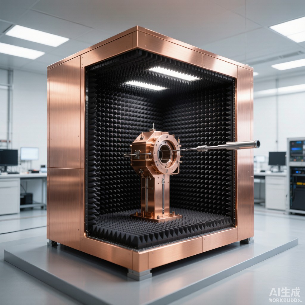
The proliferation of 5G New Radio FR2 devices operating in the 24.25-52.6 GHz millimeter-wave spectrum has fundamentally changed electromagnetic test enclosure requirements. Unlike sub-6 GHz FR1 testing, where conducted measurements suffice through coaxial co
ectors, FR2 devices integrate ante
a arrays directly into the package, mandating Over-The-Air (OTA) test methodologies. The EMI shielded test enclosure must simultaneously provide >100 dB ambient isolation from external RF, create a reflection-free measurement environment, and accommodate the precise positioning systems required for 3D spatial radiation pattern characterization. This article examines the engineering design of shielded test enclosures for 5G mmWave OTA validation.
Shielding Requirements for 5G FR2 Frequencies
Shielding Effectiveness Targets
5G mmWave OTA chambers require ambient field isolation of 100-120 dB across the 24-52 GHz band to ensure that external signals (radar, satellite downlinks, adjacent test equipment) remain 20+ dB below the noise floor of the measurement receiver. The 3GPP TS 38.508-1 specification defines the minimum OTA test environment isolation at 30 dB above the device’s EIRP; for a typical 23 dBm UE, this requires ambient levels below -107 dBm at the measurement ante
a. Achieving 100+ dB SE at 28-40 GHz demands attention to three mechanisms:
- Reflection loss: Provided by conductive chamber walls (copper or galvanized steel). At 28 GHz, skin depth in copper is 0.39 µm; a 0.5 mm copper sheet provides >120 dB reflection loss alone.
- Absorption loss: Provided by wall-mounted absorber material. Critical for preventing internal multipath reflections that corrupt OTA measurements.
- Aperture leakage: Door seams, cable penetrations, ventilation openings, and lighting fixtures. Each aperture must be designed with EMI gaskets and waveguide-below-cutoff geometry.
Chamber Wall Construction
Modular paneled chambers use 2.0-2.5 mm galvanized steel (zinc coating 275 g/m²) laminated with 1.0 mm copper foil for enhanced high-frequency performance. Panels interlock with cam-lock fasteners and are sealed with beryllium-copper finger gaskets (25-40% deflection, 200+ finger contact points per meter) at every seam. Door assemblies use double-edge knife-edge gaskets (outer conductive elastomer, i
er Be-Cu finger) with dual cam-lock closure providing >110 dB SE at 40 GHz. For tropical installations, panel corrosion protection is critical: the zinc layer must be supplemented with epoxy primer and polyurethane topcoat (200 µm total dry film thickness) to withstand 75-95% RH environments without zinc whisker formation or white rust degradation.
Absorber Material Selection for mmWave
Ferrite Tile vs Pyramidal Absorber Trade-Off
EMI test chambers employ two primary absorber technologies. For 5G mmWave OTA chambers, a hybrid approach is mandatory:
- Ferrite tile absorbers (Ni-Zn ferrite, 6.3 mm thick, µᵢ >100): Effective below 1 GHz, providing 15-25 dB reflection attenuation at 30-1000 MHz. Used as the base layer for low-frequency isolation and to meet MIL-STD-461 RE102 requirements below 1 GHz.
- Pyramidal microwave absorbers (polyurethane foam impregnated with carbon black): Effective above 1 GHz, with reflectivity performance scaling with absorber height-to-wavelength ratio. At 28 GHz (λ=10.7 mm), a 300 mm pyramidal absorber provides 40 dB reflection attenuation; at 40 GHz (λ=7.5 mm), the same absorber delivers 50+ dB.
Pyramidal Absorber Height Optimization
Absorber performance is governed by the relationship between pyramid height (h) and wavelength (λ). The IEEE 149-2021 standard defines reflectivity as a function of h/λ:
- h/λ ≥ 3: 40-50 dB reflectivity (suitable for most OTA applications)
- h/λ ≥ 5: 50-60 dB reflectivity (high-precision chambers)
- h/λ ≥ 10: 60+ dB reflectivity (metrology-grade chambers)
For 5G FR2 chambers covering 24-52 GHz, a 300 mm pyramid height achieves h/λ ≈ 2.8 at 28 GHz and h/λ ≈ 5.2 at 52 GHz, providing adequate performance across the band. Increasing to 500 mm extends useful performance below 18 GHz but adds $80-120 per m² in material cost and reduces usable chamber volume.
Tropical Climate Absorber Considerations
Carbon-impregnated polyurethane absorbers are susceptible to moisture absorption in tropical climates, with weight gain of 2-5% at 85% RH causing dielectric property drift and reflectivity degradation of 3-8 dB. Tropical installations require: (1) sealed chamber HVAC maintaining 22±2°C and 45±10% RH; (2) hydrophobic carbon impregnation treatment; (3) a
ual absorber reflectivity verification using a reference horn ante
a and vector network analyzer.
Quiet Zone Design for OTA Measurements
Direct Far-Field (DFF) Chambers
Traditional DFF chambers require the separation distance R between DUT and measurement ante
a to satisfy the Fraunhofer far-field criterion:
R ≥ 2D²/λ
where D is the largest ante
a dimension and λ is the wavelength. For a 5G smartphone with D=150 mm aperture at 28 GHz (λ=10.7 mm), R ≥ 4.2 meters. At 40 GHz, R ≥ 8.4 meters. DFF chambers for FR2 validation typically measure 6×4×3 meters (L×W×H) interior, requiring 8×6×5 meters exterior space with absorber. The quiet zone—the volume where amplitude ripple is below ±0.5 dB—is typically 300×300×300 mm at the chamber center.
Compact Ante
a Test Range (CATR) Chambers
CATR chambers use a precision parabolic reflector to collimate the spherical wave from a feed horn into a planar wavefront, creating a quiet zone at a fraction of the chamber length. A 1.5 m CATR reflector with serrated edge produces a 0.5×0.5×0.5 m quiet zone with amplitude ripple <0.3 dB and phase ripple <5° across the 26.5-40 GHz band. CATR reflectors require surface accuracy of λ/100 (0.107 mm at 28 GHz), demanding precision CNC machining from solid aluminum billet followed by hand polishing. Surface deviation beyond λ/50 introduces phase ripple that directly increases measurement uncertainty.
Near-Field to Far-Field Transformation
Near-field sca
ing chambers measure the complex (amplitude + phase) field on a planar, cylindrical, or spherical surface surrounding the DUT, then apply a Fourier-transform-based algorithm to compute far-field parameters. This approach enables testing in compact 3×2×2 m chambers but requires: (1) phase-coherent measurement (reference cha
el on VNA); (2) probe positioning accuracy of λ/20 (0.5 mm at 28 GHz); (3) scan time of 30-120 minutes per frequency point. Near-field sca
ing is preferred for production-line testing where throughput is secondary to equipment cost.
Measurement Uncertainty Budget
3GPP TR 38.901 OTA Uncertainty Components
The 3GPP TS 38.521-2 specification requires total OTA measurement uncertainty (MU) below 1.5 dB for TRP (Total Radiated Power) and below 1.8 dB for TIS (Total Isotropic Sensitivity). The uncertainty budget aggregates multiple independent sources:
| Uncertainty Source | Contribution (dB) | Mitigation |
|---|---|---|
| Quiet zone amplitude ripple | ±0.50 | CATR reflector quality, absorber performance |
| Positioner alignment error | ±0.20 | Laser alignment, rotary stage calibration |
| Measurement ante
a calibration |
±0.30 | NIST-traceable standard gain horn |
| Cable and co
ector repeatability |
±0.15 | Phase-stable cables, torque control |
| Mismatch uncertainty | ±0.25 | Impedance matching networks |
| Receiver noise floor margin | ±0.10 | Low-noise preamplifier, averaging |
| RSS Total | ±0.72 | Within 1.5 dB target |
Achieving the RSS total below 1.5 dB requires rigorous calibration of each component, environmental stability of ±1°C and ±5% RH within the chamber, and careful absorber maintenance to prevent performance degradation from dust accumulation, moisture absorption, or mechanical damage during DUT handling. For tropical Southeast Asian installations, the HVAC system must be oversized by 40-60% to handle the external sensible and latent heat load while maintaining chamber stability, with redundant dehumidification capability to prevent condensation on absorber surfaces during monsoon season transitions.



