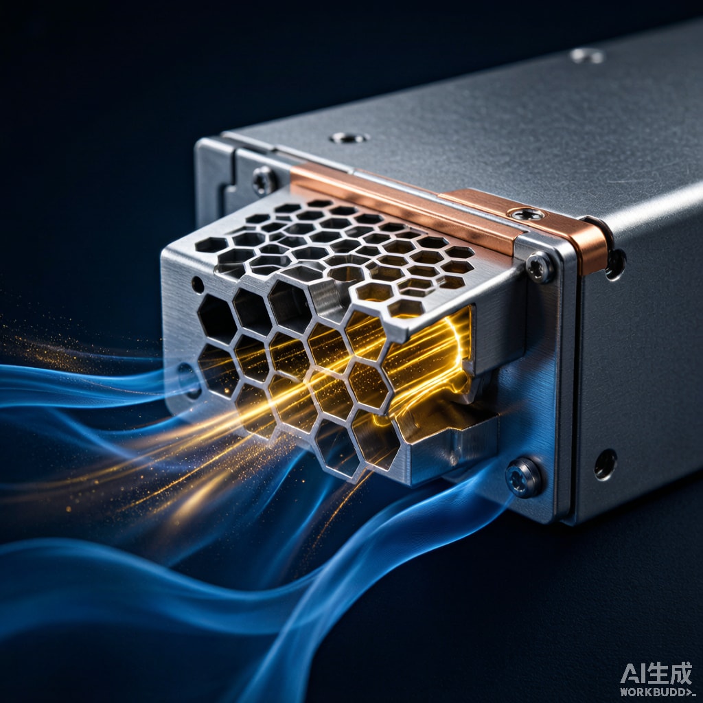
Introduction: When Forced Air Cooling Forces an EMC Problem
Modern telecom base stations, military radios, medical MRI cabinets and industrial inverters generate tens to hundreds of watts of heat, which is removed by forced-air cooling. A typical 2 kW server fan tray moves 250–500 m³/h of air through the cabinet, and the air enters and exits through perforated or louvered openings. These openings are also a tempting path for electromagnetic interference — both ingress (external noise coupling into sensitive circuits) and egress (radiated emissions escaping the enclosure and failing EMC compliance testing).
Covering the openings with a solid metal sheet restores shielding but destroys the cooling path. Covering them with a simple perforated sheet allows airflow but offers only modest shielding — a 2 mm hole array is essentially transparent to microwaves above 5 GHz. The solution is a honeycomb waveguide vent panel: a panel of small hexagonal tubes cut in a length much greater than their diameter. Each tube acts as a waveguide below its cutoff frequency, attenuating microwave signals while allowing air to flow with minimal pressure drop.
Waveguide Cutoff Frequency Theory
The Fundamental Mode in a Hexagonal Cell
A hexagonal waveguide supports the TE₁₁ mode at a cutoff frequency given by:
fc = c / (3.41 × D)
where D is the distance between parallel sides of the hexagon (the inscribed circle diameter × 2/√3) and c is the speed of light. Below this frequency, all propagating modes are evanescent — their amplitudes decay exponentially along the tube length. The attenuation per tube is:
α ≈ 27.3 × (L/D) × √(1 − (f/fc)²) dB
where L is the tube length (the panel thickness) and D is the cell size. Note that α is calculated only when f less than fc; above fc the waveguide passes the signal efficiently.
Cell Size and Panel Thickness Trade-offs
A typical shielded enclosure spec is 80 dB SE from 1 GHz to 18 GHz. With cells of D = 3.2 mm and panel thickness L = 12.7 mm (1/2 inch, a common commercial size), the cutoff frequency is:
fc = 3×10⁸ m/s / (3.41 × 3.2×10⁻³ m) ≈ 27.5 GHz
Attenuation at 10 GHz (well below cutoff) is:
α = 27.3 × (12.7/3.2) × √(1 − (10/27.5)²) = 27.3 × 3.97 × 0.93 ≈ 100 dB per cell length
This is far more than needed, which is why single panels easily deliver 80 dB SE. The challenge is balancing airflow against shielding: smaller cells give higher cutoff and better low-frequency shielding, but raise pressure drop. Larger cells let more air through but lower the cutoff frequency.
Material Selection and Manufacturing
Aluminum vs Brass vs Steel
Honeycomb vent panels are commercially available in three primary materials:
| Material | Conductivity (% IACS) | Density (g/cm³) | Cost Index | Best Use |
|---|---|---|---|---|
| 5052 aluminum | 35 | 2.7 | 1.0 | Commercial telecom, IT |
| C26000 brass | 28 | 8.5 | 1.8 | Marine, corrosion-resistant |
| Stainless 304 | 2.3 | 8.0 | 2.4 | Military, high-temperature |
| CRS tin-plated | 14 | 7.9 | 0.9 | Cost-sensitive IT |
For military EMC compliance (MIL-STD-461), brass or aluminum is standard, often with tin or nickel plating to ensure low-impedance contact along the gasket seam. For commercial telecom, 5052 aluminum is the dominant material due to its favorable strength-to-weight ratio and corrosion resistance.
Expanded vs Bonded Honeycomb
Two manufacturing methods dominate. Expanded honeycomb uses a sheet that is slit and stretched to form hexagonal cells, then stacked and bonded with adhesive. Bonded honeycomb uses corrugated sheets bonded face-to-face. Expanded is cheaper and lighter; bonded offers higher pressure rating and is preferred for military applications where vibration and shock could delaminate the stack.
Airflow and Pressure Drop
Pressure Drop Equation
Honeycomb cells approximate circular tubes for pressure drop calculations. For a single 1/2-inch panel with 1/8-inch cells, the open area ratio is typically 85–95%. Pressure drop follows:
ΔP = (f × L × ρ × v²) / (2 × Dh)
where f is the Darcy friction factor (Re-dependent), L is tube length, ρ is air density, v is face velocity, and Dh is hydraulic diameter. At typical face velocities of 2–5 m/s, pressure drop per panel ranges from 30 to 120 Pa.
Comparison with competing shield-vent technologies:
| Vent Type | Open Area | SE @ 10 GHz | ΔP @ 3 m/s |
|---|---|---|---|
| Honeycomb 1/8 cell | 85% | 85 dB | 35 Pa |
| Honeycomb 1/16 cell | 70% | 100 dB | 85 Pa |
| Perforated 2 mm hole, 3 mm pitch | 40% | 35 dB | 22 Pa |
| Knitted wire mesh | 80% | 50 dB | 18 Pa |
| Solid panel (no flow) | 0% | Infinite | Infinite |
Honeycomb offers the best SE-to-airflow ratio, which is why it is the standard for high-performance telecom and military enclosures.
Gasket Integration and Frame Mounting
Compression Gasket Selection
The honeycomb panel must be mounted to a frame with a continuous compression gasket to avoid slot leaks that degrade shielding. Beryllium-copper finger strip, conductive elastomer (filled silicone or fluorosilicone), or wire mesh gasket (Monel or tin-plated copper) are common choices. The gasket compression-deflection curve should be verified at the installed compression (typically 15–25% of free height).
Mounting Frame Design
The mounting frame must provide uniform gasket compression across the panel perimeter. A cast or machined aluminum frame with periodic captive screws and a continuous groove for the gasket is standard. The frame’s own bending stiffness should be at least 10× the gasket spring rate at the compression set point to prevent gasket gap formation under panel flexure.
Testing and Validation
IEEE 299 and MIL-STD-285
Honeycomb vent panels are validated as part of the full enclosure per IEEE 299 (1–18 GHz) or MIL-STD-285 (electric field up to 10 GHz). The panel is installed in a test aperture, and a transmitting ante
a is moved along a calibrated track while the receiving ante
a measures attenuation. Acceptance thresholds vary by application:
- Commercial EMC (FCC Part 15, EN 55032): ~40–60 dB SE at 1–6 GHz
- Telecom NEBS GR-1089: ~70 dB SE at 0.5–10 GHz
- Military MIL-STD-461: ~80–100 dB SE at 0.01–18 GHz
A good honeycomb panel delivers 80–100 dB SE in standalone testing, but the final system-level shielding depends heavily on the integrity of the mounting seam — gasket quality, fastener spacing and frame flatness.
Field Testing Considerations
After integration, site-level EMC verification with portable receivers is recommended for telecom shelters and military shelters. Common field failures include:
- Damaged honeycomb from improper handling
- Missing fasteners in the gasket seam
- Dust or paint contamination preventing gasket contact
- Compression over-setting that has permanently deformed the gasket
Application Examples
Telecom Base Station (4G/5G)
A 5G macro base station dissipates roughly 1.5 kW through forced air. Honeycomb vent panels on the cabinet doors and base provide ~80 dB SE while keeping acoustic noise low and pressure drop manageable. Tin-plated aluminum with knuckle-center mounting is the de-facto standard.
Military Vehicle Electronics
Vehicle-mounted electronics must survive shock and vibration. Expanded honeycomb panels with additional edge protection and bolted frames maintain shielding after 40g shock testing. MIL-STD-461 compliance typically requires brass or aluminum honeycomb with conductive elastomer gaskets.
Medical Imaging (MRI Room Filters)
MRI rooms require waveguide vents that maintain 100 dB SE across 1–300 MHz (RF shielding for the suite), but the cell sizing is determined by the lowest frequency of interest: a 1/4-inch cell size has fc ≈ 14 GHz, sufficient for MRI’s 64 MHz operating frequency by a wide margin.
Conclusion
Honeycomb waveguide vent panels provide a uniquely elegant solution to the conflicting demands of forced-air cooling and EMC compliance in modern electronics enclosures. By choosing appropriate cell size, panel thickness, material and gasket system, designers can achieve 80–100 dB shielding effectiveness with minimum airflow penalty. The technology is mature, commercially available in standard sizes, and validated by decades of telecom, military and medical deployment. For Southeast Asian electronics manufacturing serving demanding customers, specifying honeycomb vents at the enclosure design stage avoids costly retrofit to meet EMC compliance.



