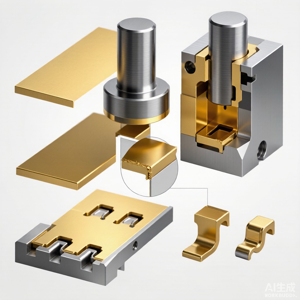
Introduction: The Cost of a Sharp Edge
In precision stamping of SMT terminals, co
ector pins, lead frames and spring contacts, edge burr is one of the most persistent quality defects. A burr is a thin ridge of material left on the stamped edge where the punch shears through the metal. Even burrs as small as 0.03 mm can cause assembly problems: increased insertion force into plastic housings, poor plating adhesion, electrical shorts, handling injuries and reduced contact reliability.
Brass strip — especially alloys C2680, C2600 and C5191 phosphor bronze — is widely used for SMT terminals because of its excellent formability, solderability and moderate cost. However, brass’s ductility also makes it prone to burr formation. This article explains how to control edge burr in brass strip stamping for electronics manufacturing.
Burr Formation Mechanisms in Stamping
The Shearing Process
When a punch descends through brass strip, the metal deforms through several zones: elastic bending, plastic deformation, crack initiation, crack propagation and final fracture. The quality of the cut edge depends on where cracks initiate in the punch and die sides and whether they meet cleanly. Ideal shearing produces a smooth burnished zone occupying 30-50% of the strip thickness, followed by a clean fracture zone with minimal burr.
Burrs form when the cracks do not meet symmetrically. If the die-side crack initiates late, material is drawn down and torn off on the die side, creating a burr. Excessive die clearance, dull tooling or insufficient hold-down force all promote this asymmetry.
Factors Affecting Burr Height
The main process variables that influence burr height are:
- Die clearance between punch and die
- Punch and die edge sharpness and wear
- Strip material hardness and thickness
- Hold-down pressure and stripper function
- Lubrication and friction
- Punch speed and impact dynamics
Die Clearance Optimization
Recommended Clearance by Material and Thickness
Die clearance is the most important controllable parameter for burr formation. For brass strip, recommended clearance as a percentage of strip thickness is:
| Brass Alloy | Thickness (mm) | Recommended Clearance (% of t) | Typical Absolute Clearance (mm) |
|---|---|---|---|
| C26000 (cartridge brass) | 0.1-0.3 | 4-7% | 0.008-0.018 |
| C26800 (yellow brass) | 0.2-0.6 | 5-8% | 0.012-0.040 |
| C5191 (phosphor bronze) | 0.15-0.5 | 6-9% | 0.012-0.035 |
Too little clearance causes secondary shear and excessive burnishing, increasing punch wear and generating rough, work-hardened edges. Too much clearance allows excessive plastic deformation before fracture, producing large burrs and rounded edges. The optimum clearance produces the cleanest fracture with the smallest burr.
Clearance Distribution
Clearance must be uniform around the entire punch periphery. Local tight spots cause accelerated wear and inconsistent edge quality. For precision terminals, die sets should be ground and assembled to maintain clearance variation below 10% of the nominal value. Using guided pillar die sets improves alignment repeatability compared to open-back inclinable presses.
Tooling Materials and Maintenance
Punch and Die Materials
For high-volume brass terminal stamping, tool steel selection directly affects edge quality consistency:
| Tool Material | Hardness (HRC) | Characteristics | Typical Application |
|---|---|---|---|
| SKD11 / D2 | 58-62 | High wear resistance, economical | General terminal stamping |
| SKH51 / M2 HSS | 62-66 | High hardness, impact resistance | High-speed progressive dies |
| Carbide (WC-Co) | 70+ | Extreme wear resistance, brittle | Long-run precision terminals |
| Powder metallurgy high-speed steel | 64-68 | Balanced toughness and wear | Critical fine-blanking |
Carbide tooling is preferred for runs exceeding 50 million strokes because it maintains edge sharpness far longer than steel, preserving burr height consistency over the die life.
Tool Wear Monitoring
Punch and die edges wear gradually, increasing burr height over time. A common control strategy is to measure burr height on first-off parts and then at defined intervals — for example, every 2 hours or every 50,000 strokes. When burr height exceeds the specification limit, tooling is sharpened or replaced.
Typical burr height specifications for SMT terminals:
- Fine-pitch co
ector pins: ≤ 0.02 mm
- Standard SMT terminals: ≤ 0.05 mm
- Power terminals and bus bars: ≤ 0.10 mm
Lubrication and Strip Handling
Stamping Lubricants
Proper lubrication reduces friction between punch, strip and die, lowering tool wear and heat generation. For brass stamping, light mineral oil or synthetic stamping oil with EP additives is commonly applied by roller coaters or drip systems. Excessive oil causes part contamination and plating defects; insufficient oil leads to galling and rough edges.
Strip Guidance and Tension
Brass strip must be fed into the die with controlled tension and precise lateral guidance. Loose strip wanders, causing uneven clearance on opposite sides of the punch and asymmetric burrs. Over-tensioned strip stretches before shearing, altering the effective clearance. Precision feeders with servo control and edge guides maintain feed accuracy within ±0.02 mm.
Post-Stamping Burr Removal
When stamping alone ca
ot meet burr specifications, secondary deburring processes are used:
- Tumbling: Batch process using ceramic media; good for small parts but may damage delicate terminal features.
- Electrochemical deburring: Dissolves burrs selectively; excellent for internal contours and fine features.
- Brush deburring: Rotating abrasive brushes remove edge burrs; suitable for flat terminals.
- Coining: A light re-strike operation compresses the burr back into the edge.
Secondary deburring adds cost and cycle time, so the preferred approach is to control burr at the source through tooling and process optimization.
Impact on Downstream Processes
Excessive burr affects several downstream operations:
- Insertion into housings: Burrs scrape plastic walls, increasing insertion force and causing particle contamination.
- Plating: Burrs create high-current-density points during electroplating, leading to nodular tin or nickel deposits and thickness non-uniformity.
- Electrical contact: Loose burr particles can bridge adjacent pins, causing short circuits in fine-pitch co
ectors.
- Handling: Sharp burrs pose cut risks to assembly operators and can damage automatic tape-and-reel packaging.
Conclusion
Edge burr control in brass strip stamping is a systems problem involving die clearance, tooling material, maintenance discipline, lubrication and feed accuracy. For SMT terminal manufacturers serving high-reliability electronics markets, maintaining burr height below 0.02-0.05 mm is achievable with proper die design and process monitoring. Investing in precision tooling and regular maintenance pays back through higher first-pass yield, fewer downstream defects and more reliable electrical contacts.



