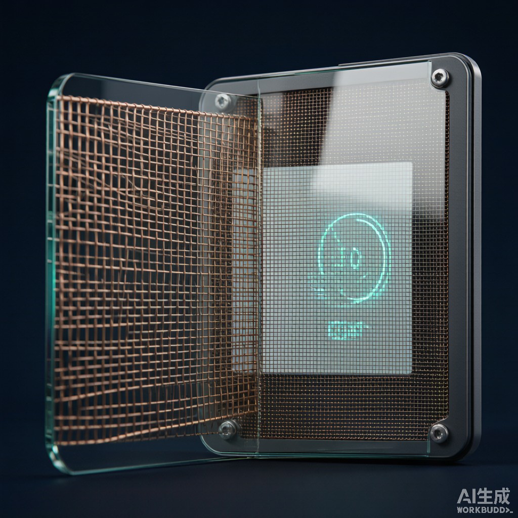
Introduction: When a Display Becomes an EMI Leak
Every display, touchscreen, and indicator window in an electronic enclosure is a potential pathway for electromagnetic interference to escape into the surrounding environment. While the metal enclosure provides 60-100 dB of shielding effectiveness across most frequencies, a transparent window — by definition, an opening in the conductive enclosure — attenuates this shielding to near zero unless specifically engineered otherwise. For industrial control equipment, medical devices, and military electronics operating in Southeast Asian manufacturing environments with dense wireless infrastructure and high electrical noise, the EMI shielding window mesh is often the limiting factor in overall enclosure compliance.
This article examines the design, materials, optical engineering, and regulatory testing of EMI shielding window meshes used in industrial control equipment displays. It covers the aperture-vs-attenuation trade-off, woven versus photolithographic mesh topologies, transparency and moiré considerations for LCD and OLED displays, capacitive touch screen compatibility, and the durability requirements for tropical climate deployment.
Shielding Mesh Aperture Physics
The Babinet Principle and Aperture Leakage
The shielding effectiveness of a mesh-covered aperture is governed by the same wave physics as any other enclosure opening — the Babinet principle describes the field transmission through a hole of any shape as the dual of radiation from a solid conductor of the same dimensions. For a rectangular window in a metallic enclosure, the attenuation at frequencies well below the waveguide cutoff is dominated by the opening size and is independent of mesh properties. At frequencies approaching and exceeding the cutoff, mesh parameters become critical.
For a mesh with square apertures of side d, the aperture cutoff frequency (the frequency above which the mesh begins to leak significantly) is:
f_cutoff = c / (2 × d)
Where c is the speed of light (3×10⁸ m/s). For example:
| Mesh Aperture (d) | Openings Per Inch (OPI) | f_cutoff | Shielding Effectiveness (at 1 GHz) |
|---|---|---|---|
| 0.50 mm | 25 OPI | 300 GHz | 75-85 dB |
| 0.25 mm | 50 OPI | 600 GHz | 60-70 dB |
| 0.10 mm | 125 OPI | 1,500 GHz | 45-55 dB |
| 0.05 mm | 250 OPI | 3,000 GHz | 35-45 dB |
| 0.025 mm | 500 OPI | 6,000 GHz | 25-35 dB |
As aperture size decreases (OPI increases), shielding effectiveness falls due to the reduced barrier thickness relative to wavelength. The 25-50 OPI range provides the best shielding performance but at the cost of optical transparency — these densities typically transmit only 40-60% of visible light.
Woven vs Photolithographic Mesh
Two distinct mesh manufacturing technologies dominate EMI shielding window applications:
Woven Wire Mesh: The traditional approach uses stainless steel or copper-clad steel wires woven in a plain or twill weave. Typical wire diameters range from 0.025 mm (for 250 OPI) to 0.10 mm (for 50 OPI). Woven mesh is cost-effective, mechanically robust, and available in large sheet sizes. The principal limitation is moiré pattern formation when the mesh grid aligns with LCD pixel arrays, producing visible interference bands that degrade display appearance.
Photolithographic Mesh: A thin metallic film (typically copper or aluminum) is deposited on a transparent substrate (glass or polycarbonate), then patterned using photolithographic etching to produce precise square or hexagonal apertures. Photolithographic mesh offers several advantages: precise aperture geometry (no weaving irregularities), pitch orientation can be deliberately rotated (typically 30-45° from LCD pixel rows to avoid moiré), and very fine pitches achievable (down to 0.025 mm aperture / 500 OPI). The trade-off is higher cost (3-10x woven) and limited sheet sizes (typically 300×400 mm maximum).
Optical Performance Engineering
Light Transmission and Display Contrast
Optical transparency of the mesh is critical for display readability, particularly in high-ambient-light industrial environments. The open area ratio (OAR) — the fraction of the mesh that is aperture rather than wire — directly determines light transmission:
| Mesh Type | OPI Range | Wire / Aperture | Open Area Ratio | Light Transmission |
|---|---|---|---|---|
| Woven (25-50 OPI) | 25-50 | 0.05-0.10 mm wire / 0.20-0.50 mm opening | 60-80% | 55-75% |
| Woven (100 OPI) | 100 | 0.04 mm wire / 0.22 mm opening | 72% | 65% |
| Woven (200 OPI) | 200 | 0.025 mm wire / 0.10 mm opening | 64% | 58% |
| Photolithographic | 100-500 | 0.005-0.020 mm metal / 0.025-0.30 mm aperture | 70-85% | 65-80% |
For industrial LCD displays operating at 200-400 nits typical brightness, the additional 25-45% light loss from the shielding mesh significantly reduces display visibility. Compensation strategies include: over-specifying display brightness by 30-50% in the bill of materials, increasing backlight power, or applying anti-reflective coatings to the outer surface of the mesh.
Moiré Pattern Control
Moiré interference patterns occur when two regular grid patterns overlap at small angular differences. In EMI-shielded displays, the mesh grid can align with the LCD pixel array or TFT backplane lines, producing visible bands or color shifts that severely degrade display quality.
The most common moiré mitigation approach is to rotate the mesh by 30-45° relative to the dominant pixel array axis. This rotation shifts the moiré pattern to a higher spatial frequency that is below the visual perception threshold. Photolithographic mesh can be rotated during the photomask design phase; woven mesh rotation is more difficult — the woven wire geometry creates directional bias that ca
ot be freely oriented.
Alternative strategies include: anti-moiré diffuser layers bonded to the i
er surface of the mesh (sacrifices some optical clarity), LCD panel anti-moiré pixel layout with offset alternating rows, and computational moiré reduction in the display controller that adjusts pixel drive signals. For critical applications, photolithographic mesh with deliberate 30° rotation typically resolves moiré concerns without optical compromise.
Capacitive Touch Screen Compatibility
Mutual Capacitance Sensing Through Mesh
Projected capacitive (PCAP) touch screens — the dominant technology for industrial HMIs — operate by measuring the mutual capacitance between orthogonal electrode traces on the touch sensor. When a finger approaches the sensor, it perturbs the local electric field and reduces the measured capacitance, producing position detection.
An EMI shielding mesh placed in front of the touch sensor must be thin enough and apertured enough that it does not disrupt the touch sensing field. The mesh wire acts as a grounded conductor that interferes with the touch field when:
Wire diameter > 0.05 mm AND wire spacing < 1.0 mm: Significant touch field distortion; “dead zones” appear above mesh wires, and touch sensitivity becomes non-uniform.
Wire diameter 0.5 mm: Minimal touch field distortion; touch performance is essentially unchanged from the bare sensor.
For PCAP touch compatibility, the practical mesh specification is ≤ 100 OPI with wire diameter < 0.03 mm — a mesh density easily achieved with photolithographic manufacturing but challenging for woven meshes (which reach 100 OPI with wire diameters around 0.04-0.05 mm).
Touch Sensitivity Calibration
Even with the correct mesh selection, touch calibration must be performed with the mesh installed in the final bezel position. The mesh introduces a small but measurable offset in touch sensitivity — typically 5-15% reduction at baseline — that the touch controller must compensate for through gain adjustment. The baseline calibration procedure should:
1. Install the touch sensor in the bezel with mesh in final position
2. Run the controller’s automatic gain calibration with no touch applied
3. Validate touch linearity using a 5-point touch test (four corners + center)
4. Document baseline sensitivity for field service reference
Be aware that finger-touch on the outer surface of the mesh and finger-touch on the mesh itself (when mesh is integral to a touchable surface) produce different signal levels. The touch controller firmware should specify whether the mesh is above or below the sensing layer in its calibration parameters.
Shielding Effectiveness Testing
IEEE 299 and MIL-STD-285 Test Protocols
The two principal testing standards for EMI shielding window performance are IEEE 299 (Standard Test Method for Measuring the Effectiveness of Electromagnetic Shielding Enclosures) and the older MIL-STD-285 (now superseded but still used for legacy applications). Both protocols place transmitter and receiver ante
as on opposite sides of the window mesh and measure attenuation across the relevant frequency spectrum.
| Frequency Band | Test Frequency Points | Acceptance Threshold (Industrial) | Test Method |
|---|---|---|---|
| VHF (30-300 MHz) | 50, 100, 200, 300 MHz | ≥ 40 dB | Log-periodic ante
a |
| UHF (300-1000 MHz) | 400, 700, 1000 MHz | ≥ 35 dB | Log-periodic ante
a |
| L-band (1-2 GHz) | 1.0, 1.5, 2.0 GHz | ≥ 35 dB | Horn ante
a |
| S-band (2-4 GHz) | 2.5, 3.5, 4.0 GHz | ≥ 30 dB | Horn ante
a |
| C-band (4-8 GHz) | 5.0, 6.5, 8.0 GHz | ≥ 30 dB | Horn ante
a |
| X-band (8-12 GHz) | 9.0, 10.5, 12.0 GHz | ≥ 30 dB | Horn ante
a |
Industrial equipment typically requires 30-40 dB minimum shielding effectiveness across the test spectrum to meet CISPR 11/CISPR 32 Class B emission limits. For military and aerospace applications (MIL-STD-461), the requirements escalate to 60-80 dB across most bands.
MIL-DTL-83528 Conductive Elastomer Gasket Integration
The mesh window edges must be bonded to the enclosure with high-integrity EMI gaskets to prevent leakage around the window perimeter. MIL-DTL-83528 specifies conductive elastomer gaskets (silver-plated copper particles in silicone or fluorosilicone binder) used in conjunction with the mesh panel. The gasket:
Compression Set Resistance: Maintains contact pressure over 10+ year service life under continuous compression
Galvanic Compatibility: Silver-plated particles can be specified for compatibility with stainless steel mesh (avoiding galvanic corrosion in humid environments)
Compression Force: Typical 5-15% compression of gasket cross-section produces the optimal contact pressure without over-stressing mesh or bezel
For Southeast Asian tropical climates where humidity regularly exceeds 80% RH, the gasket compression force should be biased toward the higher end (10-15% compression) to compensate for moisture-driven gasket softening that can reduce contact pressure over time.
Tropical Climate Durability
Corrosion Resistance of Mesh Materials
EMI shielding mesh in tropical industrial environments must resist salt-laden air, high humidity, and biological contamination. Standard mesh materials and their corrosion performance:
| Mesh Material | Salt Spray (ASTM B117) Resistance | Cost Factor | Best Application |
|---|---|---|---|
| Stainless Steel 304 | 500-1000 hours | 1.0x baseline | Indoor dry environments |
| Stainless Steel 316L | 1500-3000 hours | 1.5-2.0x | Coastal/marine tropical |
| Copper (bare) | 50-100 hours | 0.8x | Indoor, dry only |
| Tin-plated copper | 300-500 hours | 1.2x | Indoor humid |
| Nickel-plated copper | 500-1000 hours | 1.4x | General industrial |
| Silver-plated copper | 300-600 hours | 2.5x | High conductivity, dry |
For Southeast Asian industrial applications, 316L stainless steel mesh provides the best balance of corrosion resistance and EMI performance. The 2-3% molybdenum content of 316L resists pitting corrosion in chloride-containing environments far better than 304 grade.
Anti-Fungal and Anti-Biological Coatings
Mesh surfaces in tropical environments can support biological growth — bacteria, mold, and mildew colonies that not only create hygiene concerns but also increase contact resistance by forming non-conductive films on mesh surfaces. For applications with hygiene sensitivity (medical, food processing, pharmaceutical), antimicrobial coatings containing silver-ion or copper-ion additives can be specified. These coatings reduce biological growth by 90-99% over 5-year service life without significantly affecting optical transparency or shielding effectiveness.
Conclusion
EMI shielding window mesh is a critical subsystem in any electronic enclosure that requires both visual access and electromagnetic containment. The trade-off between shielding effectiveness and optical transparency is fundamental — finer meshes provide more shielding at the cost of light transmission and PCAP touch compatibility. For industrial HMI displays in Southeast Asian manufacturing environments, photolithographic mesh with deliberate rotation, 316L stainless steel or nickel-plated copper construction, MIL-DTL-83528 gasket integration, and tropical climate durability testing provide a robust solution that meets CISPR Class B emission limits while maintaining display visibility and touch responsiveness over the equipment’s operational lifetime. When the display is the operator’s primary interface to the equipment, the EMI shielding window design deserves the same engineering attention as the electronics inside.



