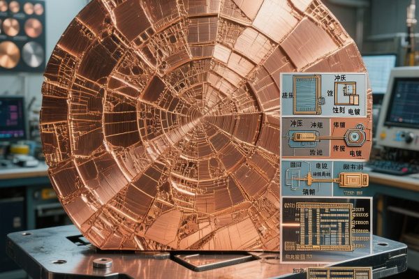
## Deep Draw Forming in SMT Component Manufacturing
Deep draw forming is a critical metalworking process for producing complex-shaped copper components used in SMT electronics—EMI shielding cans, battery contacts, co
ector shells, and thermal management housings. Unlike simple stamping that creates flat or shallow profiles, deep draw pushes copper strip into a die cavity with depth exceeding half the diameter, requiring the material to undergo significant plastic deformation without cracking or wrinkling.
For SMT manufacturers sourcing copper strip from TechMartSE, understanding the a
ealing process that enables deep draw formability is essential for specifying the right material temper, grain structure, and thickness tolerance for progressive die operations.
## Why A
ealing Is Required for Deep Draw
Copper strip arrives from the mill in various temper conditions—half-hard, hard, or spring-tempered—with limited formability. Deep draw operations demand soft temper (O60) copper with specific grain characteristics:
### The Formability Challenge
Deep drawing subjects copper to multiple simultaneous stress states:
– Radial drawing stress: Material flows radially inward from the flange toward the die opening
– Circumferential compression: Flange material compresses circumferentially as diameter reduces
– Bending-unbending: Material bends over the die radius entering the cavity, then unbends inside
– Wall ironing: Punch clearance less than material thickness causes thi
ing in the wall region
These combined stresses require copper with:
– High elongation: ≥35% for single-stage draws, ≥45% for multi-stage deep draws
– Low yield-to-tensile ratio: <0.55 ensures material yields before reaching tensile failure
– Fine equiaxed grain structure: 15-25μm grain size prevents orange peel surface defects
– Uniform mechanical properties: No directional variation from rolling texture
## A
ealing Temperature Profiles and Process Control
### Full A
ealing (O60 Temper)
Full a
ealing produces maximum formability for the deepest draws:
– Temperature range: 600-800°C (depending on alloy)
– Soak time: 30-60 minutes at target temperature
– Atmosphere: Hydrogen-nitrogen (5% H₂ / 95% N₂) to prevent oxidation
– Cooling: Controlled cooling at 50-100°C/hour through recrystallization range, then free cooling
Temperature selection by alloy:
| Alloy | A
ealing Temp | Grain Size Target | Elongation Result |
|——-|—————|——————|——————-|
| C11000 (ETP Copper) | 600-700°C | 15-25μm | 45-55% |
| C26000 (Brass 70/30) | 450-550°C | 20-30μm | 50-65% |
| C51000 (Phosphor Bronze) | 550-650°C | 10-20μm | 35-45% |
| C7025 (CuNi2Si) | 700-800°C | 15-25μm | 30-40% |
### Partial A
ealing (O50 Temper)
Partial a
ealing between half-hard and soft temper provides intermediate formability with higher strength:
– Temperature: 300-450°C for ETP copper, 250-350°C for brass
– Application: Components requiring moderate draw depth with structural rigidity
– Advantage: Higher yield strength (120-180 MPa) reduces wall thi
ing during draw
### Stress Relief A
ealing
Stress relief a
ealing at 150-250°C reduces residual stress without significant recrystallization:
– Application: Post-forming treatment to prevent season cracking in brass components
– Critical for brass: C26000 brass is susceptible to stress corrosion cracking in ammonia environments—stress relief is mandatory for automotive and industrial SMT applications
## Grain Size Control: The Key to Surface Quality
Grain size directly determines deep draw surface quality and mechanical consistency. Coarse grains (>50μm) produce orange peel surface defects—irregular, rough surface texture visible after drawing that makes the component unsuitable for plating or precision assembly.
### Grain Size Measurement and Specification
– ASTM E112: Standard method for determining average grain size
– Target for deep draw: ASTM grain size number 7-8 (15-25μm equivalent)
– Measurement technique: Intercept method on metallographic cross-section
– Acceptance criteria: G7-G8 with ≤10% grains exceeding G5 (50μm)
### Grain Growth Prevention
Excessive a
ealing temperature or time causes grain growth:
– Rule: A
ealing temperature should be 50-100°C above recrystallization threshold, not higher
– Recrystallization temperatures: ETP copper ~250°C, brass ~300°C, phosphor bronze ~350°C
– Warning: Holding at 700°C for 2+ hours produces G3-G4 grain size (100-150μm)—unusable for deep draw
Practical control: Specify maximum a
ealing temperature on purchase orders, and request grain size certification from your copper strip supplier. TechMartSE provides mill test certificates with grain size data for deep draw-grade copper strips.
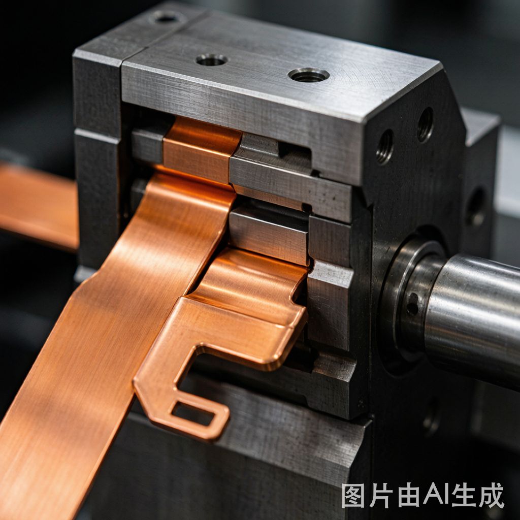
## Progressive Die Deep Draw Station Design
Multi-stage progressive dies perform deep drawing in sequential stations:
### Station Sequence for EMI Shielding Can (3mm depth)
1. Blank station: Pierce and blank the initial flat disc
2. First draw station: Draw to 1.5mm depth (draw ratio 0.55)
3. Second draw station: Redraw to 2.5mm depth (draw ratio 0.65)
4. Third draw station: Final draw to 3.0mm depth with wall ironing
5. Trim station: Trim flange to final dimensions
6. Form station: Form snap-fit tabs and locating features
### Draw Ratio Calculation
– Draw ratio = blank diameter / punch diameter
– Maximum first draw ratio: 0.48-0.55 for a
ealed copper (deeper ratios cause tearing)
– Redraw ratio: 0.60-0.75 per subsequent station
– Total draw ratio: Product of all station ratios determines maximum achievable depth
### Material Thickness Selection
– Starting thickness: 0.15-0.30mm for typical SMT shield cans
– **Wall thi
ing**: 10-20% reduction through ironing stations
– Final wall thickness: Minimum 0.10mm for structural integrity
– Flange thickness: Maintains starting thickness (flange does not iron)
## A
ealing Between Draw Stages (Inter-Draw A
ealing)
For very deep draws exceeding 5mm depth, inter-draw a
ealing between progressive die stations is necessary:
– When required: Total draw ratio exceeds 0.55 × 0.75 × 0.75 = 0.31 (deep draws with large diameter reduction)
– Process: Coil strip a
ealed between die stations, then re-fed for subsequent draws
– Temperature: Same as full a
ealing profile (600-700°C for copper)
– Production impact: Increases cycle time 3-5x, only justified for high-value components
### Alternative: Transfer Die Approach
Transfer dies move the part between stations without coil a
ealing:
– Advantage: Maintains material temperature from previous station deformation heat
– Application: Moderate draw depths (3-5mm) where residual deformation heat supplements formability
– Speed: 30-60 strokes/minute, suitable for high-volume SMT component production
## Quality Inspection for Deep Drawn Copper Components
### Visual Inspection Criteria
– Surface quality: No orange peel, no wrinkles, no draw lines visible under 10× magnification
– Edge condition: Clean trimmed edges, no burrs >0.02mm
– Dimensional accuracy: ±0.05mm on depth, ±0.03mm on wall diameter
### Functional Testing
– Spring-back test: Snap-fit tabs must maintain engagement force within ±15% specification
– Plating adhesion: Post-draw nickel/gold plating must pass ASTM B571 adhesion test
– Solderability: Per J-STD-002 Category 3 (wetting <2 seconds after steam aging)
## Conclusion
Copper strip deep draw a
ealing is fundamental to producing complex SMT components with reliable formability. By controlling a
ealing temperature profiles, grain size targets (G7-G8), and draw ratio sequences, manufacturers can achieve consistent deep-drawn copper parts—EMI shielding cans, co
ector shells, and thermal housings—with excellent surface quality and dimensional accuracy. TechMartSE supplies a
ealed copper strip grades (C11000, C26000, C51000) with certified grain structure and mechanical properties optimized for progressive die deep draw operations, supporting Southeast Asian SMT manufacturers in producing high-quality formed components.