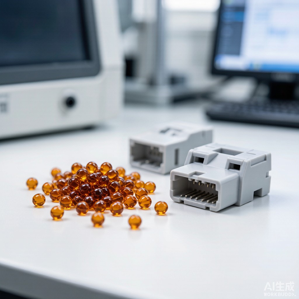
Surface-mount technology co
ector housings must survive the thermal rigors of lead-free reflow soldering—peak temperatures of 245-260°C maintained for 60-90 seconds—while maintaining precise dimensional tolerances (typically ±0.05 mm on terminal pockets) and adequate mechanical strength for terminal insertion and retention. Polyphenylene sulfide (PPS), a semi-crystalline high-performance thermoplastic, has emerged as a premier material for this application when reinforced with glass fiber. This article examines the material properties, processing parameters, and performance characteristics of glass-fiber reinforced PPS modified plastic pellets for SMT reflow-compatible co
ector housings.
PPS Material Fundamentals for Electronic Co
ectors
Molecular Structure and Thermal Properties
PPS (poly(p-phenylene sulfide)) is a linear aromatic polymer with repeating -C₆H₄-S- units. Its rigid aromatic backbone and strong C-S bonds confer exceptional thermal stability:
- Melting point: 280-285°C (well above lead-free reflow peak temperatures)
- Glass transition temperature: 85-95°C (amorphous regions)
- Heat deflection temperature (HDT): 110°C (unfilled) to >260°C (GF40)
- Continuous use temperature: 200-220°C (UL RTI rating)
- Thermal decomposition onset: >400°C in air
Unlike PA66 (melting point 260°C), PPS does not approach its melting point during reflow, eliminating the risk of housing distortion, terminal floating, or dimensional creep that plagues lower-temperature plastics in SMT assembly.
Crystallization Behavior
PPS is a slow-crystallizing polymer with maximum crystallization rates occurring at 120-140°C. In injection molding, rapid cooling through this range can trap amorphous content (typically 30-50% in as-molded parts). Post-mold a
ealing at 180-200°C for 1-2 hours increases crystallinity to 55-65%, improving dimensional stability, chemical resistance, and heat deflection temperature. For co
ector housings, a
ealing is strongly recommended—and often mandatory—for applications requiring tight post-reflow dimensional tolerances.
Glass-Fiber Reinforcement Effects
Mechanical Property Enhancement
Glass fiber reinforcement transforms PPS from a brittle, low-strength material into an engineering thermoplastic suitable for structural electronic components:
| Property | Unfilled PPS | PPS-GF30 | PPS-GF40 | Test Standard |
|---|---|---|---|---|
| Tensile strength (MPa) | 80-90 | 160-180 | 190-220 | ASTM D638 |
| Flexural modulus (GPa) | 3.3-3.8 | 10-12 | 13-16 | ASTM D790 |
| Notched Izod impact (J/m) | 20-30 | 80-100 | 90-110 | ASTM D256 |
| HDT at 1.82 MPa (°C) | 110 | 250-260 | 260-270 | ASTM D648 |
| CTE (×10⁻⁶/°C) | 50-60 | 20-25 | 18-22 | ASTM E831 |
| Mold shrinkage (%) | 1.2-1.6 | 0.3-0.5 | 0.2-0.4 | ASTM D955 |
GF30 vs GF40: Selection Criteria
The choice between 30% and 40% glass fiber loading involves trade-offs between mechanical performance, processability, and cost:
- PPS-GF30: Preferred for complex housings with thin walls (0.3-0.5 mm) and intricate geometries. Lower viscosity improves flow into fine terminal pockets and reduces mold wear. Cost advantage of 15-20% over GF40.
- PPS-GF40: Selected for high-pin-count co
ectors (>100 positions) requiring maximum stiffness and minimal post-insertion creep. Higher modulus reduces terminal pocket deformation under insertion force. Slightly reduced impact resistance compared to GF30 due to fiber-fiber interaction.
SMT Reflow Compatibility
Peak Temperature Survival
The defining qualification for SMT co
ector housings is survival through lead-free reflow without dimensional or cosmetic degradation. PPS-GF30/40 housings demonstrate excellent performance:
| Reflow Profile Parameter | Typical Value | PPS-GF Response |
|---|---|---|
| Preheat ramp | 1.5-2.5°C/s to 150°C | No thermal shock cracking; CTE mismatch with glass fiber accommodated |
| Soak zone | 150-180°C for 60-120s | Moisture outgassing complete; no blistering if properly dried |
| Peak temperature | 245-260°C for 30-60s | No melting, distortion, or terminal floating; HDT >260°C ensures rigidity |
| Cooling ramp | 2-4°C/s to 100°C | No warpage if mold design balances shrinkage; crystallinity increases slightly |
Moisture Absorption and Pre-Baking
Despite PPS’s reputation for low moisture absorption (0.02-0.05% at equilibrium, 23°C/50% RH), glass-fiber reinforced grades absorb slightly more due to fiber-matrix interfacial regions. In Southeast Asian warehouse conditions (30°C/80% RH), equilibrium moisture content reaches 0.08-0.12%. While this is far below PA66-GF30 (2.5-3.0%), pre-baking before reflow remains critical:
- Pre-bake conditions: 120-130°C for 2-4 hours in dry air or nitrogen.
- Maximum moisture before reflow: <0.05% (measured by Karl Fischer titration or halogen moisture analyzer).
- Floor life after baking: 72 hours at <60% RH; 24 hours at <80% RH (SE Asian ambient).
Failure to pre-bake can result in cosmetic blistering at weld lines and surface defects, though PPS is far more tolerant than nylon-based materials.
Injection Molding Process Optimization
Processing Parameters
| Parameter | PPS-GF30 | PPS-GF40 | Notes |
|---|---|---|---|
| Melt temperature | 300-330°C | 310-340°C | Above 340°C risks polymer degradation and gas formation |
| Mold temperature | 130-160°C | 140-170°C | Higher mold T promotes crystallization and surface finish |
| Injection pressure | 80-120 MPa | 100-150 MPa | GF40 requires higher pressure for equivalent flow length |
| Hold pressure | 60-90 MPa | 80-110 MPa | Prevents sink marks in thick sections |
| Back pressure | 5-15 MPa | 5-15 MPa | Higher back pressure improves fiber dispersion |
| Screw speed | 50-100 rpm | 50-80 rpm | Lower speed reduces fiber breakage |
Mold Design Considerations
Co
ector housing molds for PPS-GF require specific design adaptations:
- Gate design: Submarine or fan gates preferred over pinpoint gates to reduce fiber orientation stress at terminal pockets. Multiple gates may be necessary for large housings (>50 mm) to minimize weld line strength reduction (typically 30-50% of base strength at weld lines).
- Venting: PPS decomposition gases (SO₂, H₂S, thiophenes) require generous venting (0.01-0.02 mm depth) to prevent burn marks and short shots.
- Draft angles: 0.5-1.0° per side minimum; PPS’s high stiffness makes ejection challenging without adequate draft.
- Corrosion-resistant tooling: PPS releases corrosive decomposition products at high temperatures. H13 or S136 stainless steel with nitriding or PVD coating extends mold life from 50,000 to 200,000+ shots.
Terminal Retention and Electrical Performance
Insertion and Retention Force
The primary mechanical function of a co
ector housing is to retain metal terminals with sufficient force to prevent withdrawal during mating/unmating and vibration, while allowing reasonable insertion force during assembly:
| Parameter | Specification | PPS-GF30/40 Performance |
|---|---|---|
| Terminal insertion force | 3-8 N per terminal | Consistent within ±15% due to low mold shrinkage |
| Terminal retention force | >15 N per terminal (min) | 20-35 N typical; creep resistance maintains >80% after 1,000h at 85°C |
| Housing deflection under insertion | <0.05 mm | High flexural modulus minimizes deflection |
| Post-reflow retention force | >80% of initial | Typically 85-95% retained after 3× reflow cycles |
Dielectric Properties
PPS-GF maintains stable electrical insulation across the temperature and humidity ranges encountered in SMT assembly and field operation:
- Dielectric constant (Dk): 3.8-4.2 at 1 MHz (stable from -40°C to +150°C)
- Dissipation factor (Df): 0.001-0.002 at 1 MHz
- Volume resistivity: >10¹⁶ Ω·cm
- Dielectric strength: 15-20 kV/mm
- Comparative tracking index (CTI): 175-225V (PLC 2-3)
The low and stable Dk/Df makes PPS-GF suitable for high-speed signal co
ectors operating to several GHz, though for mmWave applications (>10 GHz), unfilled or low-Dk filled grades may be preferred.
Material Comparison for SMT Co
ector Housings
| Property | PPS-GF30 | PA66-GF30 | PBT-GF30 | LCP-GF30 |
|---|---|---|---|---|
| Reflex peak temp (°C) | 260+ | 245 (marginal) | 250 | 270+ |
| HDT 1.82 MPa (°C) | 250-260 | 250 | 210 | 260-280 |
| Moisture absorption (%) | 0.02-0.05 | 2.5-3.0 | 0.08-0.15 | 0.02-0.04 |
| Mold shrinkage (%) | 0.3-0.5 | 0.4-0.8 | 0.3-0.6 | 0.05-0.15 |
| Relative cost | 1.8× | 1.0× | 1.2× | 2.5× |
| Reflow cycles survived | 3-5 | 1-2 | 2-3 | 5+ |
Conclusion
Glass-fiber reinforced PPS modified plastic pellets provide an optimal balance of thermal stability, mechanical strength, dimensional precision, and electrical insulation for SMT reflow-compatible co
ector housings. PPS-GF30 offers the best combination of processability and performance for most applications, while PPS-GF40 addresses the most demanding high-pin-count designs. Proper moisture management through pre-baking, optimized mold design for fiber-filled materials, and post-mold a
ealing to maximize crystallinity are essential process controls. For Southeast Asian manufacturing environments, PPS’s inherent moisture resistance provides a significant reliability advantage over PA66-based alternatives, reducing field failures from humidity-induced dimensional changes and hydrolysis degradation.



