Why Copper Strip Shunts Beat Discrete Resistors in High-Current BMS
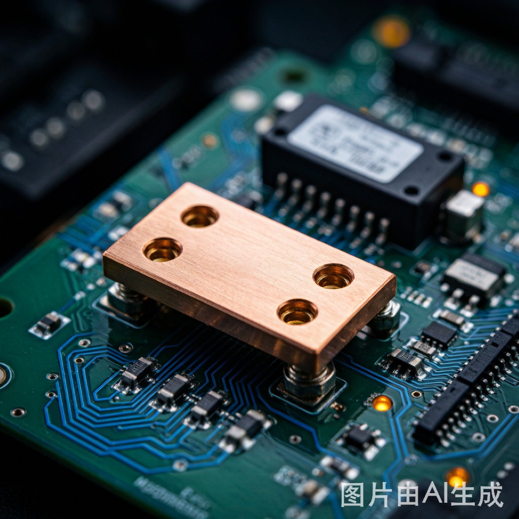
Battery management systems in electric vehicles, energy storage cabinets, and industrial UPS units routinely measure currents from tens to hundreds of amperes. Discrete SMT current-sense resistors become expensive, thermally limited, and mechanically fragile above 5 W–10 W dissipation. A better approach is to use a bare copper strip shunt integrated directly into the power path. Because copper combines low resistivity, predictable temperature behavior, and high solderability, it delivers a cost-effective sensing element that survives board-level assembly without special handling.
The main challenge is that the absolute resistance of a copper trace or strip is extremely low—often below 0.5 mΩ. At 100 A, even a 0.2 mΩ shunt produces only 20 mV of signal, so every micro-ohm of contact or lead resistance corrupts the reading. This is why a Kelvin (four-wire) co
ection is mandatory.
Kelvin Co
ection: Eliminating Lead and Contact Resistance
A Kelvin shunt separates the high-current power path from the low-current sense path. Two pads carry the full load current; two smaller pads tap the voltage drop across a precisely defined section of copper. Because the sense traces carry negligible current, their contact resistance and solder-joint IR drop do not influence the measurement.
Key layout rules include:
- Sense tap placement: Locate the i
er edges of the sense pads exactly at the boundary of the calibrated shunt length. Even a 0.2 mm offset changes resistance by several micro-ohms.
- No shared copper: Route sense traces independently back to the amplifier inputs; do not merge them into power planes.
- Symmetry: Keep positive and negative sense paths identical in length and geometry to cancel thermoelectric offsets.
- Guard rings: On high-resolution designs, place a low-impedance guard around sense traces to reduce leakage in humid Southeast Asian climates.
Material Selection: C11000, C19400, and Manganin Trade-offs
| Alloy | Conductivity (% IACS) | TCR (ppm/°C) | Typical Use Case |
|---|---|---|---|
| C11000 (ETP) | 101 | +3,930 | Low-cost, high-current busbars with software compensation |
| C19400 | 65 | +2,300 | Lead frames needing moderate strength and solderability |
| Manganin | 7 | ±15 | Precision laboratory shunts, not typical SMT |
Most production BMS designs prefer C11000 copper strip because it is inexpensive, widely available in tight thickness tolerances, and compatible with standard reflow profiles. The high TCR is managed in firmware rather than by exotic alloys.
Thermal Design and TCR Compensation
A 0.2 mΩ copper shunt carrying 100 A dissipates 2 W. Without heat spreading, the strip can rise 40 °C–60 °C above ambient, shifting resistance by 8 %–12 %. Three techniques control this drift:
- Copper plane heat sinking: Co
ect the shunt to internal copper planes through multiple vias to spread heat.
- Temperature sensing: Place an NTC or digital temperature sensor within 5 mm of the shunt element and apply a first-order correction: RT = R25[1 + α(T − 25)].
- Calibration at operating temperature: Calibrate each unit at a known current and temperature; store gain and offset in non-volatile memory.
Layout and Solder Joint Best Practices
Use at least 1 oz outer copper and 2 oz where possible for the power path. Stencil apertures for the high-current pads should cover ≥70 % of the pad area with a 1.2:1 area ratio to ensure void-free solder joints. Underfill is generally u
ecessary for shunts, but a conformal coat protects sense traces from ionic contamination in tropical environments.
By combining a Kelvin four-wire geometry with robust thermal management, SMT copper strip shunts deliver current measurement accuracy within ±1 % over temperature at a fraction of the cost of precision resistors.



