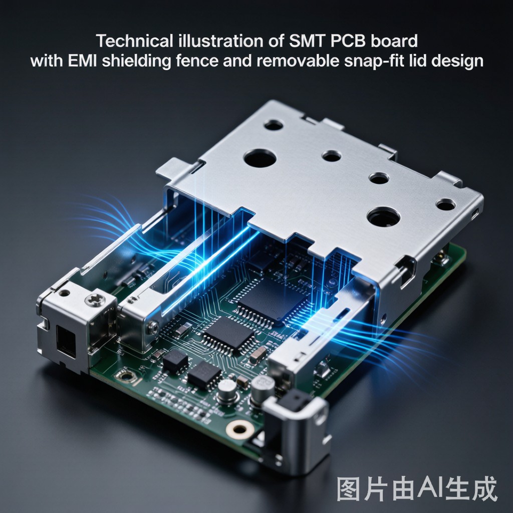
Introduction: The Rework Paradox in Board-Level EMI Shielding
Board-level EMI shielding is the last line of defense in electromagnetic compatibility (EMC) design. After enclosure-level shielding, cable filtering, and PCB layout optimization have been exhausted, a metal shield soldered directly onto the PCB over sensitive RF circuits or noisy digital ICs provides the final 10–30 dB of isolation needed to pass radiated emissions (CISPR 32, FCC Part 15) or immunity (IEC 61000-4-3) testing.
But a shield that is permanently soldered to the board creates a painful paradox: the circuits it protects become inaccessible for rework, probing, and failure analysis. If a QFN IC under a soldered shield can develops a solder joint crack during thermal cycling qualification, the entire shield must be desoldered — a process that risks PCB pad lifting, adjacent component damage, and voiding the board’s warranty for EMC re-certification. The removable-lid shielding fence addresses this paradox by separating the shielding function into two parts: a perimeter fence permanently soldered to the PCB, and a removable lid that snaps, clips, or presses onto the fence — providing both shielding integrity and rework access.
This article compares the two approaches across shielding effectiveness, rework access, thermal management, assembly process, and total cost of ownership for SMT PCB designs in RF modules, IoT devices, 5G small cells, and other wireless products where both EMC compliance and serviceability are required.
Shielding Effectiveness: Physics and Practical Performance
One-Piece Solder-Attached Shield Can
A one-piece shield can is a drawn or folded metal enclosure (typically 0.2–0.3 mm thick tin-plated steel, nickel silver C7521, or stainless steel) with an open bottom that is soldered to a continuous ground trace surrounding the shielded circuit on the PCB. The solder joint creates a continuous, low-impedance electrical co
ection around the entire perimeter.
Shielding effectiveness of a well-designed one-piece can:
| Frequency | Typical SE (dB) | Limiting Factor |
|---|---|---|
| 100 MHz | 60–80 | Aperture leakage (ventilation holes, if any) |
| 1 GHz | 50–70 | Aperture leakage dominates |
| 3 GHz | 40–60 | Slot resonance between ground vias if spacing >λ/20 |
| 6 GHz | 30–50 | Ground via spacing critical (must be ≤λ/10 = 5 mm at 6 GHz) |
| 10 GHz | 25–45 | Cavity resonance within shield volume (λ/2 modes) |
The primary shielding degradation mechanism in one-piece cans above 3 GHz is the periodic slot ante
a formed by the ground vias stitching the perimeter pad to the internal ground plane. If via spacing exceeds λ/20 (2.5 mm at 6 GHz), the gaps between vias act as slot ante
as that leak RF energy. The solution — increasing via density to ≤2 mm spacing — adds PCB fabrication cost and routing congestion but is essential for millimeter-wave shielding.
Removable-Lid Shielding Fence
A shielding fence system consists of:
- Perimeter fence: A continuous metal wall (0.15–0.3 mm thick, typically tin-plated steel or nickel silver) with surface-mount solder tabs on its bottom edge, soldered to the PCB ground trace during SMT reflow. The fence forms the permanent, soldered portion of the shield.
- Removable lid: A metal cover with spring fingers, dimples, or a snap-fit geometry around its perimeter that makes electrical contact with the fence wall. No solder — the lid is held in place by mechanical spring force and can be removed with a pry tool or specialized removal tool.
Contact impedance — the Achilles’ heel of removable lids:
The shielding effectiveness of a removable-lid fence is limited by the contact impedance between the lid’s spring fingers and the fence wall. Each spring finger creates a discrete contact point with a contact resistance of 5–20 mΩ (new) to 20–100 mΩ (after thermal cycling and vibration aging). At microwave frequencies, this contact impedance translates to a leakage path.
The total transfer impedance of a fence with N spring fingers, each with contact resistance R_c, spaced s apart, at frequency f:
Z_T ≈ (R_c × s) / (N × δ_skin), where δ_skin is the skin depth in the fence material at frequency f.
For a typical 30 × 30 mm fence with 24 spring fingers (4 per side × 4 sides = 16 total), s ≈ 7.5 mm between contacts. At 3 GHz with R_c = 10 mΩ (new condition):
- δ_skin (tin-plated steel, σ ≈ 10⁶ S/m) ≈ 9 μm at 3 GHz
- Z_T ≈ (0.01 Ω × 0.0075 m) / (16 × 9 × 10⁻⁶ m) ≈ 0.52 Ω — this is orders of magnitude higher than a soldered joint
This analysis reveals the fundamental trade-off: a removable lid can NEVER match the shielding effectiveness of a solder-attached one-piece can because the mechanical contact impedance — even when perfectly clean and new — is 10²–10⁴ times higher than a soldered joint.
Comparative Shielding Effectiveness
| Frequency | One-Piece Can SE (dB) | Removable-Lid Fence SE (dB) | Delta (dB) |
|---|---|---|---|
| 100 MHz | 60–80 | 50–65 | 10–15 |
| 1 GHz | 50–70 | 40–55 | 10–15 |
| 3 GHz | 40–60 | 30–45 | 10–15 |
| 6 GHz | 30–50 | 20–35 | 10–15 |
| 10 GHz | 25–45 | 15–30 | 10–15 |
The 10–15 dB deficit is consistent across frequency — it represents the contact impedance penalty that no amount of spring-finger design optimization can eliminate. For applications where every dB of shielding matters (radar receivers, spectrum analyzers, precision RF test equipment), one-piece solder-attached cans remain the only option. For applications where the circuit’s own intrinsic noise immunity or emission control provides adequate margin, the 10–15 dB penalty of a removable lid is often acceptable.
Rework Access: The Decisive Advantage of Removable Lids
Rework Process Comparison
| Rework Scenario | One-Piece Shield Can | Removable-Lid Fence |
|---|---|---|
| Access time to shielded component | 3–8 minutes (desoldering shield, hot air + vacuum pickup) | 5–10 seconds (pry off lid with tool) |
| Risk of PCB damage during shield removal | Moderate to high — pad lifting (5–15% probability per removal), adjacent component reflow, trace delamination | Near zero — lid is mechanical only, no heat applied |
| Post-rework shield re-attachment | Hand-solder (poor SE) or re-reflow (logistically complex for single board) | Snap lid back on (instant, full SE restoration) |
| Re-certification requirement | Yes — hand-soldered shield has different SE than production reflowed shield | No — lid contact impedance unchanged by removal/replacement cycle |
| Maximum practical rework cycles | 1–3 before PCB damage probability becomes unacceptable | 10–50+ before spring finger fatigue reduces contact force |
The rework access advantage of removable-lid fences is overwhelming: 3–8 minutes and 5–15% PCB damage risk versus 5–10 seconds and near-zero risk. For products that require field service (replacing a failed module on a base station or automotive ECU), the removable lid is not merely convenient — it determines whether the module is economically repairable or must be scrapped and replaced entirely.
Thermal Management: Cooling Access Through the Lid
Thermal Comparison
Board-level shields create enclosed, stagnant air volumes that trap heat from shielded ICs. A typical 3.3V regulator dissipating 0.5W inside a 25 × 25 × 5 mm shield can (internal volume 3.1 cm³, no ventilation) reaches a junction temperature of 90–110°C at 25°C ambient — unacceptable for consumer electronics reliability targets.
Thermal management options differ fundamentally between the two shield types:
| Thermal Feature | One-Piece Can | Removable-Lid Fence |
|---|---|---|
| Ventilation holes (stamped) | ✓ (0.5–2.0 mm holes, 30–50% open area — trade-off with SE) | ✓ (same as one-piece, plus lid can be perforated independently) |
| Thermal interface material (TIM) to lid | Difficult — must be assembled before shield placement | ✓ Easy — apply TIM to IC, install lid, compress TIM under lid spring force |
| Lid as heatsink (thick metal, fins) | Limited — shield can thickness 0.2–0.3 mm carries negligible lateral heat | ✓ — Lid can be thicker (0.5–1.0 mm aluminum or copper), stamped with fins, acting as a functional heatsink |
| Post-assembly TIM inspection | Impossible (shield is opaque, soldered) | ✓ — Remove lid, inspect TIM compression pattern, reinstall |
The removable lid’s ability to double as a TIM-compression heatsink is a powerful thermal advantage. A 0.5 mm aluminum lid with 1 mm tall stamped fins, thermally coupled to a shielded IC via a 0.5 mm gap pad (3 W/m·K), can reduce junction-to-ambient thermal resistance by 40–60% compared to a passively cooled one-piece can.
Assembly Process and Cost Comparison
Manufacturing Cost Elements
| Cost Element | One-Piece Shield Can | Removable-Lid Fence |
|---|---|---|
| Part cost (30×30 mm shield) | $0.08–0.20 | $0.15–0.35 (fence) + $0.10–0.25 (lid) = $0.25–0.60 total |
| SMT placement (pick-and-place) | 1 feeder position + 1 placement operation | 2 feeder positions + 2 placement operations (fence + lid placed separately) |
| Soldering | Standard reflow — no additional process step | Standard reflow for fence. Lid NOT soldered — installed after reflow as a separate manual or automated station |
| Post-reflow lid attachment | Not applicable | $0.02–0.10 per unit (manual press-fit) or automated lid-placing machine ($15,000–30,000 capital, $0.005–0.01 per unit for high volume) |
| Total per-unit cost (100k volume) | $0.15–0.30 | $0.35–0.75 |
The removable-lid fence system costs 2–3× more per unit than a one-piece can. At 100,000 units per year, the additional cost is $20,000–45,000 — a non-trivial BOM adder. This cost must be justified by one of three business cases: (1) rework cost avoidance (each avoided board scrap saves $50–200 in fully burdened PCB assembly cost); (2) field serviceability (replacing a failed RF module instead of scrapping a $500–5,000 product); or (3) faster development and EMC debug cycle time (removable lid allows probing and modification without desoldering).
Selection Decision Matrix
| Design Requirement | Recommended Shield Type | Rationale |
|---|---|---|
| Maximum shielding (>60 dB at 1 GHz) | One-piece can | No contact impedance penalty; full perimeter solder joint |
| Production test access (RF probing) | Removable lid | Lid removed for test, reinstalled for final assembly |
| Field-serviceable product | Removable lid | Module replacement without desoldering |
| Cost-sensitive consumer product (<$50 BOM) | One-piece can | Lowest unit cost; no serviceability expected |
| High thermal dissipation (>1W per IC under shield) | Removable lid with TIM-heatsink lid | Thick metal lid as heat spreader/heatsink |
| IoT sensor module (battery powered, sealed for life) | One-piece can | No rework expected; cost and shield margin prioritized |
| 5G small cell / base station radio | Removable lid (RF sections) + one-piece can (power supply) | Hybrid: serviceable RF with removable lids; non-serviceable power with cans |
| Automotive ECU (15-year life, vibration) | One-piece can (preferred) or removable lid with secondary retention | Can is inherently vibration-proof; removable lid requires positive retention mechanism (screw or secondary clip) |
Conclusion
The choice between a removable-lid EMI shielding fence and a one-piece solder-attached shield can is fundamentally a trade-off between shielding performance and accessibility. One-piece cans deliver 10–15 dB higher shielding effectiveness across 100 MHz – 10 GHz by eliminating the mechanical contact impedance that is inherent to any removable lid interface. Removable-lid fences sacrifice this shielding margin to gain: (1) rework access in 5–10 seconds versus 3–8 minutes with 5–15% PCB damage risk; (2) the ability to use the lid as a functional heatsink via TIM compression; and (3) field-serviceable shield removal without EMC re-certification. The removable-lid fence costs 2–3× more per unit ($0.35–0.75 vs $0.15–0.30) — this premium must be justified by rework cost avoidance, field serviceability, or development time savings. For consumer products where the first-pass yield exceeds 98% and no field service is designed, the one-piece can is the engineering and economic default. For products requiring development debug access, production RF test probing, or field module replacement, the removable-lid fence transforms the shield from a barrier into a design-for-test and design-for-service enabler.



