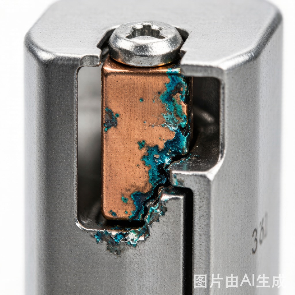
Introduction: The Invisible Failure Mode in Shielded Electronics
EMI shielding cans are essential components in modern electronics, containing electromagnetic emissions from sensitive circuits and protecting them from external interference. The shielding effectiveness (SE) of a metal can—typically 40–80 dB depending on material, thickness, and aperture design—depends critically on low-impedance electrical contact between the can and the PCB ground plane. This contact is usually achieved through solder joints, conductive gaskets, or spring finger contacts. In humid tropical environments characteristic of Southeast Asia, these grounding contacts become sites for galvanic corrosion—a slow but relentless degradation process that can increase contact impedance from milliohms to ohms over months or years, silently eroding shielding effectiveness until electromagnetic compliance failures or functional interference emerges.
Galvanic Corrosion Fundamentals at Shielding Interfaces
The Galvanic Series in Practical Electronics
Galvanic corrosion occurs when two dissimilar metals are in electrical contact in the presence of an electrolyte (moisture film). The metal with the more negative (anodic) electrode potential corrodes preferentially, while the more noble (cathodic) metal is protected. In EMI shielding applications, the common metal combinations and their galvanic relationships are:
| Shielding Can Material | PCB Pad Finish | Galvanic Risk | Anode (Corrodes) | Severity |
|---|---|---|---|---|
| Tin-plated steel (SPTE) | ENIG (Au/Ni/Cu) | High | Steel (Fe) | Severe |
| Tin-plated steel | OSP (Cu) | High | Steel (Fe) | Severe |
| Tin-plated steel | HASL (Sn/Cu) | Medium | Steel (Fe) / Sn | Moderate |
| Brass (C26800) | ENIG (Au/Ni/Cu) | Medium | Brass (Zn) | Moderate |
| Stainless steel (SUS304) | ENIG (Au/Ni/Cu) | Low | Minimal | Low |
| Nickel silver (C7521) | ENIG (Au/Ni/Cu) | Low | Minimal | Low |
| Copper (C11000) | OSP (Cu) | None | N/A (same metal) | Negligible |
Tin-plated steel cans—the most common and cost-effective EMI shielding solution—are also the most vulnerable to galvanic corrosion. The steel substrate (Fe, E° = -0.44 V) is significantly more anodic than the copper PCB pad (Cu, E° = +0.34 V), creating a driving potential of 0.78 V. Even though the tin plating (Sn, E° = -0.14 V) provides a barrier, any pinhole, scratch, or solder joint discontinuity exposes the underlying steel to galvanic attack.
Corrosion Rate Acceleration in Tropical Climates
The galvanic corrosion rate is governed by the availability of electrolyte at the contact interface. In temperate climates (15–25°C, 40–60% RH), thin moisture films form only during brief condensation events, and the a
ual corrosion rate at a steel-copper interface is typically 5–20 μm/year. In tropical Southeast Asian climates, the combination of sustained high humidity (>75% RH for 8+ hours daily), elevated temperatures (30–38°C), and atmospheric chloride contamination creates conditions where:
- Continuous moisture films persist on metal surfaces for 4,000–6,000 hours per year
- The electrolyte film conductivity is 5–10× higher due to dissolved chlorides and sulfates
- Temperature acceleration (Arrhenius) approximately doubles reaction rate per 10°C
- The net corrosion rate at exposed steel-copper interfaces reaches 50–200 μm/year
At 100 μm/year, a 0.3 mm thick tin-plated steel shielding can wall can be perforated in approximately 3 years—well within the expected product lifecycle of consumer electronics (5+ years) or industrial equipment (10+ years).
Failure Modes and Shielding Degradation
Contact Impedance Rise
As galvanic corrosion products (iron oxides/hydroxides, Fe₂O₃·nH₂O, FeOOH) accumulate at the grounding contact interface, they form a resistive layer between the shielding can and the PCB ground plane. The contact impedance trajectory typically follows three phases:
- Phase 1 (0–6 months): Stable contact resistance <5 mΩ. Corrosion initiated but insufficient product accumulation to affect impedance.
- Phase 2 (6–18 months): Gradual increase to 50–500 mΩ. Corrosion products begin to disrupt metal-to-metal contact spots. Shielding effectiveness may degrade by 3–8 dB at frequencies above 1 GHz.
- Phase 3 (18+ months): Exponential increase to >10 Ω. Large areas of the contact interface are separated by insulating corrosion layers. Shielding effectiveness drops by 15–30 dB, potentially causing EMI compliance failure.
Physical Contact Loss
For spring finger contacts and conductive gaskets (not soldered joints), corrosion product volumetric expansion (iron rust is 3–6× the volume of consumed steel) can physically push the shielding can away from the PCB pad, reducing contact force. Below the minimum contact force (typically 50–100 g for fingerstock gaskets), the contact becomes intermittent, causing signal integrity problems that are extremely difficult to diagnose.
Solder Joint Degradation
For soldered shielding cans, galvanic corrosion at the steel-tin interface beneath the solder fillet can cause progressive weakening of the solder joint. As the steel substrate corrodes, the solder loses its mechanical anchor and the joint becomes susceptible to vibration-induced cracking. This failure mode is particularly insidious because the can appears externally intact while the grounding path has been electrically severed.
ASTM B117 Salt Spray Testing and Correlation
ASTM B117 is the standard accelerated corrosion test method, exposing specimens to a continuous neutral salt spray (5% NaCl, 35°C, pH 6.5–7.2). While B117 does not perfectly replicate real-world tropical conditions (it overrepresents chloride exposure and underrepresents humidity cycling), it provides a useful comparative metric for evaluating shielding can material and finish options.
| Shielding Can Configuration | Hours to Red Rust (B117) | Equivalent Field Life (Tropical) | Assessment |
|---|---|---|---|
| Bare SPTE steel, no plating | 2–6 | 3–6 months | Unacceptable |
| SPTE, 2 μm tin plating | 24–48 | 1–2 years | Marginal |
| SPTE, 5 μm tin plating | 72–120 | 2–4 years | Acceptable (consumer) |
| SPTE, Ni + Sn duplex plating | 200–400 | 5–8 years | Good (industrial) |
| Brass C26800, bare | 48–96 | 2–3 years | Marginal (dezincification) |
| Stainless SUS304, passivated | >1000 | >10 years | Excellent |
| Nickel silver C7521, bare | 500–800 | 8–12 years | Very good |
For consumer electronics with 3–5 year expected lifecycles in tropical climates, tin-plated steel with minimum 5 μm tin over a 1–2 μm nickel underplate is adequate. For industrial or medical equipment with 10+ year lifecycles, stainless steel or nickel silver shielding cans are strongly recommended despite their higher cost.
Mitigation Strategies
1. Material Compatibility Engineering
The most effective strategy is eliminating the galvanic couple entirely. Using copper or copper-alloy shielding cans (C11000, C7521) with copper or ENIG PCB pads eliminates the driving potential for galvanic corrosion. When tin-plated steel cans must be used for cost reasons, ensure the PCB pad finish is also tin-based (HASL or Immersion Sn) rather than ENIG, reducing the galvanic potential difference.
2. Protective Coatings on Grounding Contacts
Applying a conformal coating (acrylic, silicone, or polyurethane per IPC-CC-830) over the assembled shielding can-to-PCB interface seals the contact against moisture ingress. However, coating must be carefully masked from active contact zones in gasketed designs. For soldered cans, a thin layer of epoxy edge-fill along the solder joint perimeter provides superior moisture sealing compared to conformal coating alone.
3. Contact Design Optimization
For gasketed shielding designs, specify beryllium copper (BeCu) or stainless steel fingerstock gaskets rather than tin-plated steel gaskets. BeCu gaskets have higher contact force per unit deflection and are inherently resistant to galvanic corrosion when paired with copper PCB pads. Ensure the gasket contact pressure exceeds 100 g per contact point to maintain gas-tight interfaces that resist moisture intrusion.
4. Enclosure-Level Protection
Design the product enclosure to minimize internal humidity. Use IP54 or higher enclosure sealing for tropical installations. Incorporate desiccant compartments sized for the internal free volume (typically 5–10 g of silica gel per liter of enclosure volume). For forced-air-cooled equipment, ensure that intake air passes through a hygroscopic filter element to reduce humidity ingress.
Conclusion
Galvanic corrosion at EMI shielding can grounding contacts is a significant but often overlooked reliability risk for electronics deployed in humid tropical environments. The progressive increase in contact impedance can silently degrade shielding effectiveness over months, eventually causing EMI compliance failures or functional interference. By understanding the galvanic relationships between shielding can materials and PCB pad finishes, selecting compatible material combinations, specifying adequate plating thickness verified by ASTM B117 testing, and implementing protective coatings and enclosure-level moisture control, manufacturers can ensure that EMI shielding maintains its designed effectiveness throughout the product lifecycle—even in the most challenging tropical environments.



