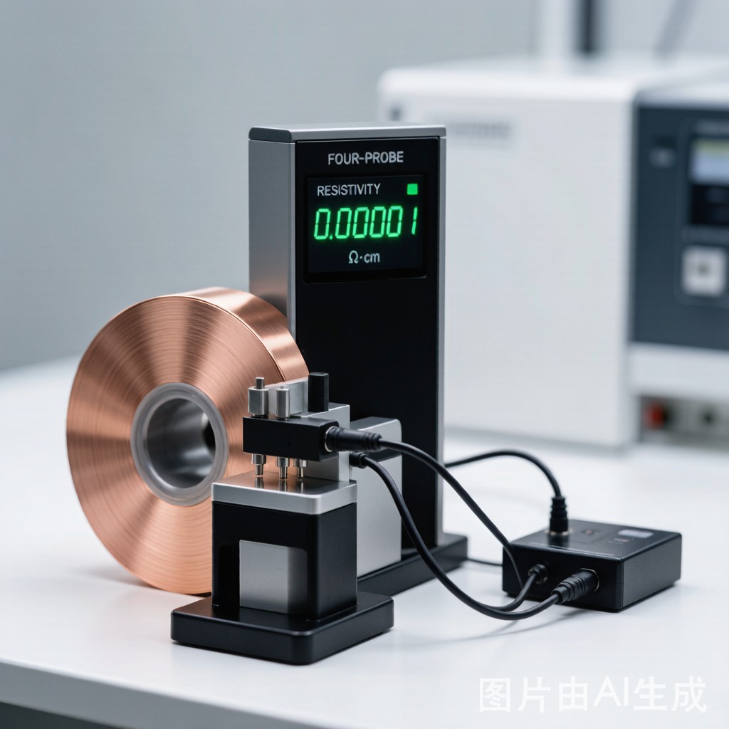
Why Four-Point Probe Measurement Matters
Electrical resistivity is one of the most critical quality parameters for copper foil, strip, and bus bar materials used in SMT lead frames, PCB laminates, and EMI shielding applications. Even small variations in resistivity—caused by alloying impurities, cold work, grain structure, or plating defects—can affect signal integrity, power dissipation, and thermal performance in finished electronic assemblies.
The four-point probe (4PP) method is the industry standard for measuring sheet resistance of thin conductive films and strips. Unlike two-point methods, the 4PP configuration eliminates contact resistance errors by separating current injection from voltage measurement, enabling accurate determination of resistivity in materials with resistances below 1 mΩ·cm.
Measurement Principle and Geometry
In a linear four-point probe arrangement, four equally spaced collinear probes contact the sample surface. A constant current (I) is passed through the outer two probes, and the voltage drop (V) is measured across the i
er two probes. For an infinitely thin, infinitely wide sheet, the sheet resistance (Rₛ) is:
Rₛ = 4.532 × V / I (for probe spacing s = 1.00 mm)
The correction factor 4.532 derives from the geometric series solution to the potential distribution around point current sources on a 2D conductor. For bulk samples where thickness (t) is significant, the volume resistivity (ρ) is:
ρ = Rₛ × t = 4.532 × (V / I) × t
ASTM F84 and SEMI MF84 Standards
ASTM F84 (Standard Test Method for Measuring Resistivity of Silicon Wafers) and SEMI MF84 (Test Method for Measuring Resistivity of Silicon Wafers) are the foundational standards, with adaptations for metallic thin films through the Van der Pauw method and collinear probe configurations. Key requirements include:
- Probe spacing uniformity within ±0.5% of nominal spacing
- Contact force between 20–150 grams per probe, depending on sample hardness
- Current selection low enough to avoid self-heating (typically <10 mA for thin copper foils)
- Sample temperature measurement within ±0.5°C for accurate temperature correction
Probe Configurations and Their Applications
Collinear (In-Line) Probes
The standard configuration for rectangular copper strips and foils. Probe spacing of 1.00 mm or 1.59 mm (1/16 inch) is common. The collinear arrangement is simple to align and ideal for continuous production line testing where samples move past fixed probes on a conveyor.
Van der Pauw Method
For arbitrarily shaped samples or when the strip width is comparable to probe spacing, the Van der Pauw method uses four contacts on the periphery of the sample. The resistivity is determined from two resistance measurements (R_AB,CD and R_BC,DA) without requiring knowledge of sample dimensions. This is ideal for small coupon samples cut from production coils for laboratory qualification testing.
Non-Contact Eddy Current Methods
For very thin copper foils (<18 μm) where mechanical probe contact may scratch or deform the surface, eddy current sensors provide a non-contact alternative. These induce a magnetic field in the sample and measure the resulting eddy current decay, which correlates with conductivity. While less precise than 4PP (±2% vs ±0.5%), eddy current probes are ideal for inline 100% inspection of rolled a
ealed (RA) and electrodeposited (ED) copper foil during CCL manufacturing.
Temperature Correction and Environmental Factors
Copper resistivity increases with temperature at approximately +0.39% per °C. All 4PP measurements must be corrected to a standard temperature (typically 20°C or 23°C) using:
ρ₂₀ = ρ_T × [1 + 0.00393 × (T − 20)]⁻¹
where T is the measurement temperature in °C and ρ_T is the measured resistivity. For tropical manufacturing environments where ambient temperatures reach 30–35°C, uncorrected measurements can overstate resistivity by 4–6%, potentially causing false rejection of conforming material.
Humidity affects measurements only indirectly by promoting surface oxidation. A thin copper oxide film (Cu₂O or CuO) has much higher resistivity than the base metal and can artificially inflate sheet resistance if probes contact oxidized regions. Pre-test surface cleaning with IPA or light abrasion is recommended for high-precision measurements.
Interpreting Resistivity Data for Quality Control
Detecting Plating Defects
Electroplated nickel or tin layers on copper substrates increase the effective sheet resistance because nickel (resistivity ~6.9 μΩ·cm) and tin (~11.5 μΩ·cm) are far less conductive than copper (~1.68 μΩ·cm). A 2 μm nickel underplate can increase the sheet resistance of 35 μm copper foil by 8–12%. Uniformity mapping across a 300 mm wide coil can reveal plating thickness variations, edge effects, or bare spots where the substrate shows through.
Grain Structure and Cold Work Indicators
Electrical resistivity is sensitive to crystal defects. Cold-rolled copper (H04 temper) has ~2–3% higher resistivity than fully a
ealed copper (O temper) due to dislocation density. A gradual increase in resistivity across a production coil may indicate incomplete a
ealing or cross-contamination with higher-resistivity alloys. Sudden jumps often signal material mix-ups (e.g., C19400 instead of C11000) that can be caught before downstream processing.
Practical Implementation in Production QA
For incoming material inspection, measure resistivity at three positions across the coil width (center, 1/4 point, edge) and at both ends of the coil. Compare against the alloy specification: C11000 (ETP copper) should read 1.724 μΩ·cm at 20°C; C19400 (iron-bearing) is ~2.30 μΩ·cm; C19210 (high-conductivity) is ~1.75 μΩ·cm. Establish control charts with ±3σ limits to detect process drift.
Inline eddy current systems should be calibrated against 4PP master samples daily, with automatic temperature compensation and alarm thresholds set at ±5% of the nominal value for the specific alloy grade. Any coil exceeding the threshold is flagged for manual 4PP verification and metallurgical review.
Conclusion
Four-point probe resistivity measurement is a fast, non-destructive, and highly sensitive quality assurance tool for copper foil and strip. When implemented with proper temperature correction, standardized probe geometry, and statistical process control, it provides early detection of material defects, alloy mix-ups, and plating inconsistencies that would otherwise compromise SMT assembly performance and reliability.



